All sources indicate that Atanasoff made a "Proof of Concept" device to obtaining funding for his proposed calculating machine.
| Image and text from "The First Electronic Computer: The Atanasoff Story" by Burks & Burks - courtesy of Alice R. Burks |
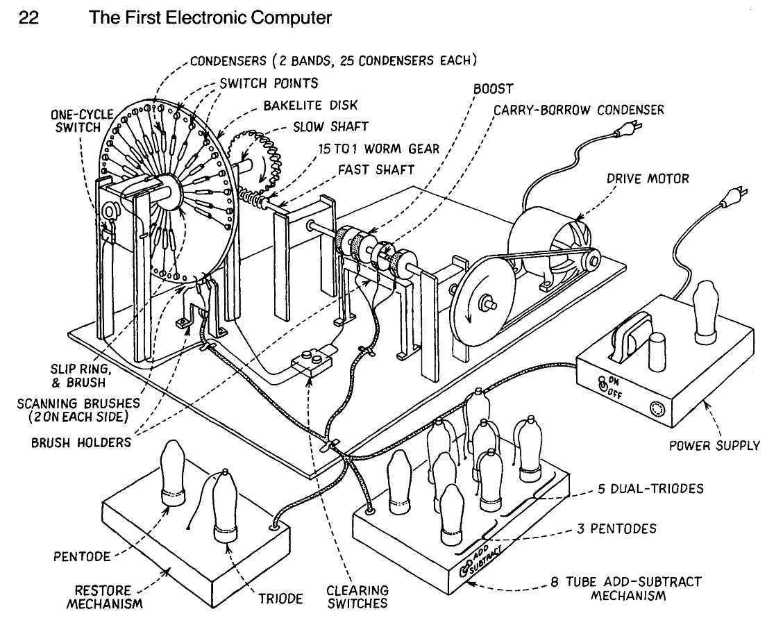
| Fig. 5. Drawing of 1939 model. This drawing (now slightly modified) was made for court proceedings about thirty years after the fact. The model had two storage bands, each with twenty-five condensers, on the outer faces of a large disk; one band represented an abacus or coefficient of the counter drum, the other that of the keyboard drum. It had an add-subtract mechanism, served by a single carry-borrow condenser, to add or subtract the two abaci, and also a mechanism to perform the restore, but not the shift, function. The model proved that Atanasoff's principles of electronic computation were practicable. On the basis of this success and the manuscript he finished in August, 1940, he received a grant to complete his computer. |
The book "The First Electronic Computer: The Atanasoff Story" gives the above information, but other than schematics of the circuits used in the final calculator, give no information about how to demonstrate the device - such as showing a successful addition, or even that a value on a capacitor is correctly refreshed.
SO - there could be a question "Did Atanasoff actually demonstrate that this prototype device actually worked - or did he do a super sales job, wave his hands at the completed device, and assure the "venture capitalists" ;-)) that the final version would be just fine?? ;-))
Background
| A fundamental problem to demoing the "Proof of Concept" Device is to
The shown "Proof of Concept" device does not show input or output mechanisms. This implies manual insertion of voltages - "1"s and "0"s, and the manual verification that the proper "1"s and "0"s are indeed present. This may sound simple, but voltages leak off of everything, including the (paper) capacitors used to store the voltages/information. (This is why the Atanasoff invention, refresh, used today in the memory of your computer.) The voltage leakage is through internal and external resistances associated with the capacitors. Lets assume that we use 0.01 ufd capacitors rated at 400 volts. (The pictured capacitors would seem to fit the above parameters.) |
Some Problems Demoing the "Proof of Concept" Device
|
The Demos, then and now
While I am trying to dig into 70 year old history -
I would like to imagine how the "Proof of Concept" device could be effectively
demonstrated in two environments:
- A 1939 Demo of the Proof of Concept device to "venture capitalists"
You almost need some crude form of oscilloscope - maybe available in Iowa before WWII? You could use the "One Cycle Switch" to discharge a capacitor making a saw-tooth wave for the horizontal deflection - and use a signal from the brushes to the refresh amplifier to drive the vertical. This could yield a stable repeating pattern of pulses from the spinning disc of capacitors. You could selectively look at either set of capacitors. It could be believable -The above ignores the problem of placing test patterns onto the capacitors.
- A 2010 Demo of the Proof of Concept device to "venture capitalists"
The "One Cycle Switch" used above, and the "Boost" signal, could provide synchronization to all kinds of devices to:- a) input signals to the refresh amplifier to set "1"s and "0"s on the capacitors
- b) output signals to a dual channel scope, selected display lamps, computer monitor, ...
The inputs and displays would require attention, but not be beyond most modern hardware (or software) hackers. The major problem would be selecting which available technology and graphical user interface. ;-))
- a) input signals to the refresh amplifier to set "1"s and "0"s on the capacitors