Amateur Seismology
for about 5 years, starting around 1970 :-))
by Ed Thelen ed@ed-thelen.org* Amateur Seismology *
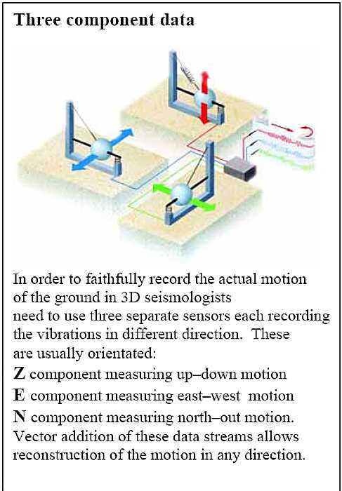
Well, at least you get to relax and watch nothing happen a lot ;-)) This paper presents ideas, and is not a how-to construction document Modern (since the 1980s) commercial broad band seismometers are three dimension, force-balanced (use electro-dynamical feedback) and are smaller and much easier to install and operate. Examples are here, a leaflet (local copy).
"Unlike traditional seismic sensors, molecular-electronic ones use a liquid inertial mass."
A Seismology History from USGS, (local copy) including that in the early 1900s, "B.B. Galitzen develops the the first electromagnetic seismograph ..." widely used even today, and discussed in this paper.
Earthquake Information Bulletin, 1972 Jan/Feb
Mars, Molten at Core from Wall Street Journal, July 23, 2021
Table of Contents
Introduction
Narrative
Background
What style and direction sensitivity to build?
Sensor Design Considerations
Sensor Mounting and Adjustments
Amplifier and/or Signal Converter
An Unusual Interference
Time Tagging
Recording
Another type, using LED with LDR Sensor with Data Logging
An amateur looks at professional needs and equipment
Toward Sensor Linearization
Another Amateur Machine, Lyle Denny, Jan 30, 2017
Wanted smaller, Marcel-Marie LeBel, April 15, 2018
amateur seismology community is very small, Alain Michaud, Nov 8, 2021 < info @ alainmichaud . ca > Introduction
A "seismograph" can be thought of as having three parts:
|
|
Our family moved to California - "Earthquake Country" - in 1970.
Having read a number of "do-it-yourself-seismology" articles in "Scientific American"
and hearing of a nice integrated circuit amplifier, I started building.
Soon I had a seismometer, an amplifier (I was an electronics junkie),
and a then a recording unit, all working well.
OK, I was not too demanding ;-)) I told my Los Angeles cousin Rita that I was interested in seismology - Rita had gone to school with Tom Sanders of Palo Alto. Tom was interested in amateur seismology. I contacted Tom, and found that he was a member ofthe "World Amateur Seismological Society" ( WASS ) and was the current treasurer and also editor/publisher of its quarterly journal. Soon I was a member and contributing articles. I seemed to be the only member contributing articles. (There were about 180 "members" paying annual dues (mostly going into postage for the quarterly newsletter) but not saying or volunteering anything.) Tom tired of publishing the WASS journal, and offered me the editorship - I seemed the only "victim". After about two years of rather solitary work, as treasurer, author, editor, and publisher, I too tired of publishing the WASS journal- but could not find a victim - and closed WASS. After a few years I "down sized" and gave the WASS notebooks of publications to Larry Cochrane of the Redwood City Public Seismic Network. Preparing to write this article, I asked Larry for the WASS notebooks, but he too had "down sized", and they are no more :-(( |
| I am a techie - encouraged by a gift of the monthly "Scientific American" magazine while in high school in 1946 - and a faithful reader of its column "Amateur Scientist" until about 1991 when the liberal arts types ( who didn't seem to know high school science ) took over the magazine, and the "Amateur Scientist" column was no longer supported. One of many fascinating articles in "Amateur Scientist" was how to build a seismograph sensitive in a horizontal direction to very low frequency waves, like a wave that takes 10 seconds. The output signals needed amplification to be seen an/or recorded. At the time, vacuum tube amplifiers were in, transistors flaky and expensive. The project seemed too much bother. We moved to earthquake country, lots of earthquake activity, in 1972, just about the same year a lovely little integrated transistor amplifier, the 741, became available, for about $ 2 instead of say $300 for the previous hot, power hungry, troublesome, vacuum tube direct current amplifiers. All of the above, plus meeting Tom Sanders ( above ) got me started building ;-)) |
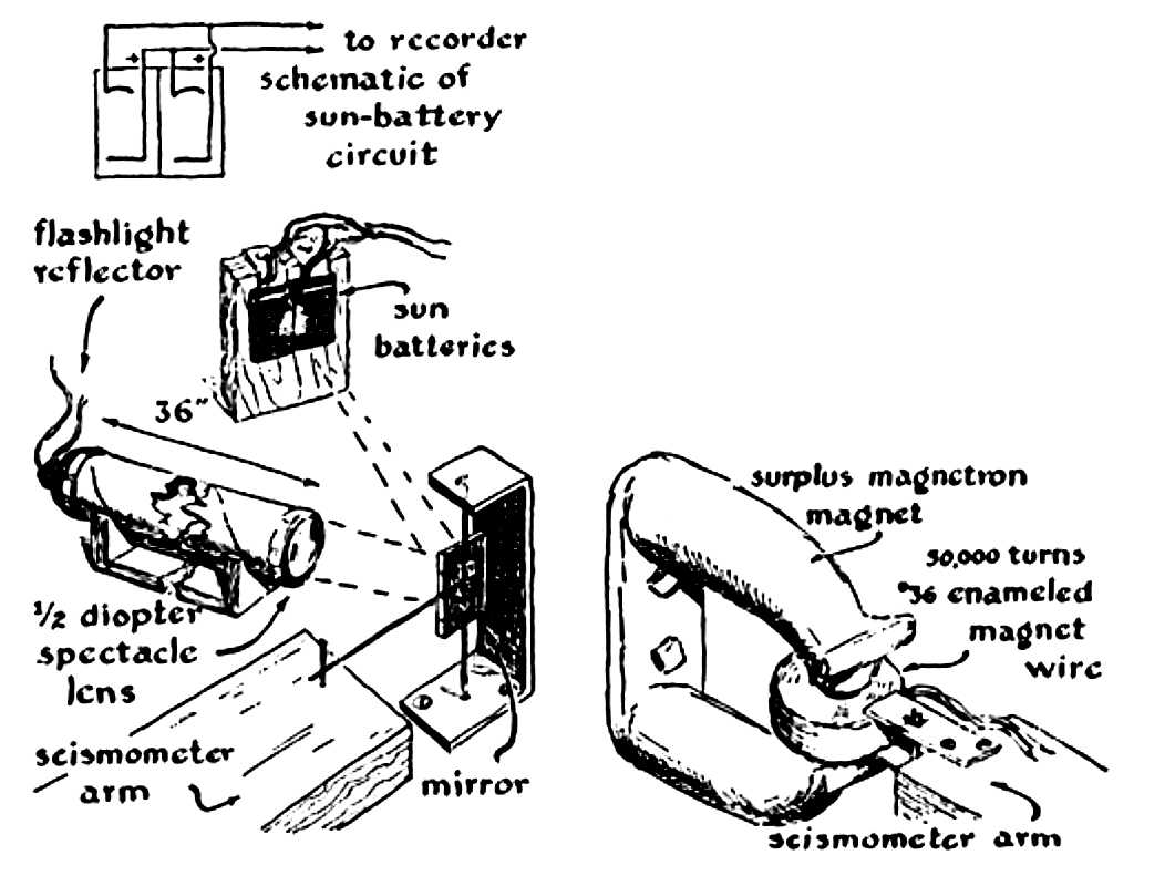
- http://en.wikipedia.org/wiki/Seismometer - http://www.geophys.uni-stuttgart.de/oldwww/seismometry/man_html/node15.html and for that lovely little DC amplifier, the 741 ( not cutting edge any more ;-) - http://www.ti.com/product/lm741 There is also the "style" of the sensor. One of the early seismometers used a mirror on a wire. The mirror would be an inertial mass twisted by the wire shaking with the earth. A beam of light bouncing from the mirror would darken moving photographic film to record the earthquake. This system was used by Richter to define the "Richter Scale". Using a coil interacting with a magnetic field is widely used now, in part because of availability of convenient and stable electronic amplifiers. It is easy to get a signal from a coil near a moving magnet, * but * to get a reasonably linear calibrated output over a reasonable range of movement requires some engineering and care - well beyond the scope of this little paper. Positioning one edge of your round coil of wire in the center of your magnetic field will hopefully at least get your polarity consistent with the motion, even if not very linear :-)) |
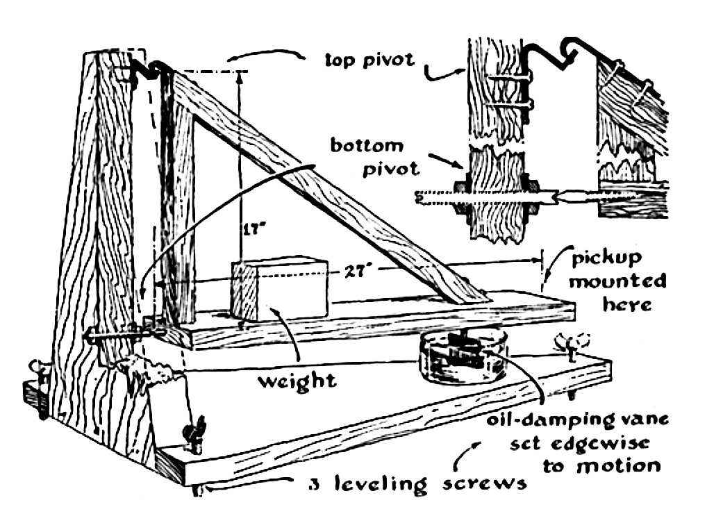
OK, now we are into it - the goal - a home built "garden gate" type horizontal seismometer with as long a period as practical.
Basic Idea
|


Seismometer Location
|
|
This is where we moderns have it all over the ancients
( we had vacuum tubes from the 1920s through the 1960s , current semi-conductors are even better ;-))
The June 1953 Amateur Scientist a schematic of a vacuum tube amplifier with 30 ufd coupling capacitors
and 5 meg grid resistors - but you don't want to deal with that !!
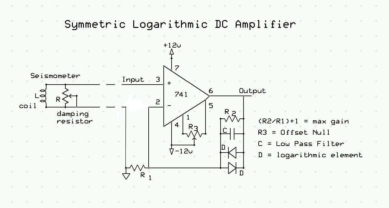
I used the 741 op amp in the 1970s, great in its day, but by current standards had large offset (to be manually
adjusted out), high temperature drift, and high input current.
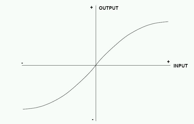
I used a non-inverting logarithmic amplifier circuit similar to this. Values are not shown as this is not a construction article.
- for analog output, very nice chopper stabilized amplifiers with negligible offset and drift for $1 - for digital output, very high resolution A to D converters, don't need amplifiers for $10 In either case, pay attention to the application notes, and also use twisted pair wires from the seismometer to the electronics to reduce noise and hum pickup. Shielded twisted pair is even better ;-)) Using a connector at each end eases handling and transportation problems. I am assuming that you don't want to become an electronics bug complete with soldering iron, so lets just buy an already made board with components already installed and tested, with output to your PC for easy recording and possible post-processing the seismic activity you collect. Larry Cochrane of the Redwood City Public Seismic Network has designed and sold ready made electronics for years. He also links to free PC software that operates this equipment and records and presents the seismic information. A note on these wonderful high resolution Analog to Digital Converters - say 24 bit ADCs - A 24 bit ADC can (should ;-)) resolve its legal input values into over 16 million different digital values. It can produce useful digital output from a 5 microvolt wave - plenty good enough for almost anyone ;-)) And it outputs to USB to interface to any computer made in the past 10 years ;-)) I'm stressing digital output because the continual changing paper and other servicing of analog outputs is really a drag !! |
|
Maybe once a week, the amplifier would have an odd periodic offset about 6 times a minute,
for maybe 10 or 15 minutes, then back to normal.
What in the world ??
The effect could be considered my bad - my little DC amplifier, with diodes,
was completely unshielded. Even worse, the construction was not compact - the wire leads of the
741 were unclipped, just tack soldered onto what ever components it was connected to.
The diodes were in a chain, I didn't want to clip any lead so that I could make changes, on the cheap.
|
|
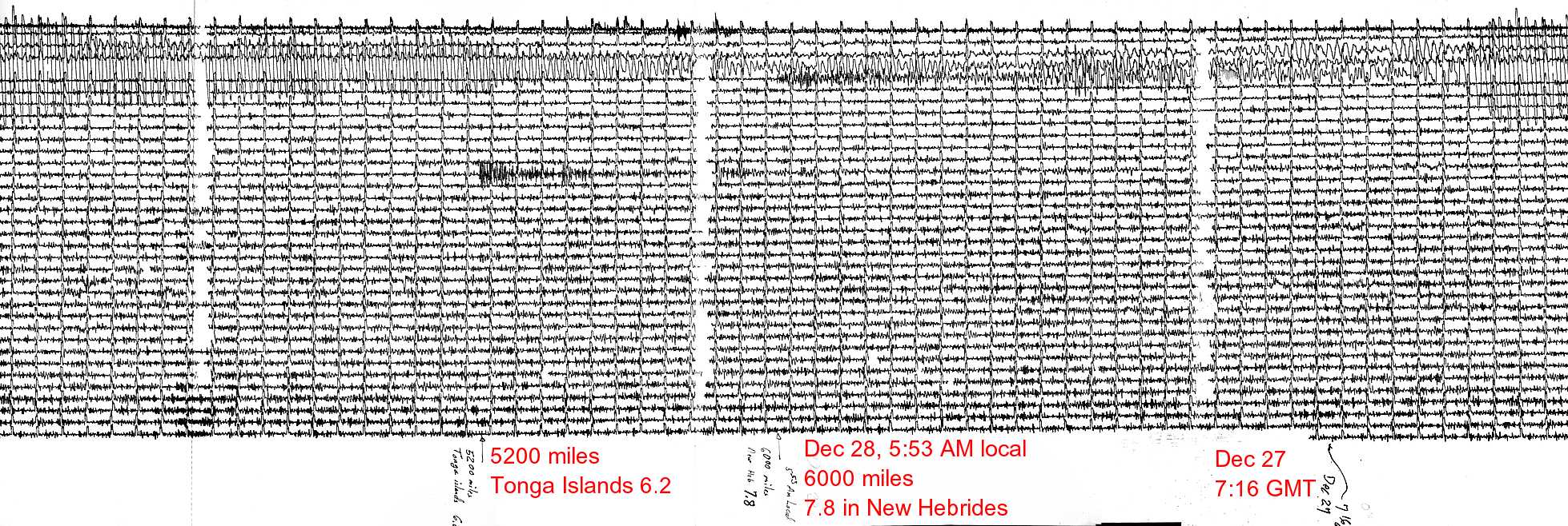
For anything more serious than amusing your neighbors with your squiggles,
you should include time information into your data. In the 1970s I used a little synchronous timer motor
that rotated once a minute, operating a switch. This I adjusted by listening to WWV on a cheap short wave radio.
I also had an electric clock set to "Greenwich Mean Time" for convenience :-))
Now fancy GPS equipment, accurate to nanoseconds, is available for about $80 -
And speaking of time - since seismology is world wide folks like to use what used to be called Greenwich Mean Time ( GMT ). Time turns out to be rather complicated - in the 1970s, a friend gave me a 40 page document document describing time used in earth satellites :-| There are at least UT1, UT2, and GPS times :-| And leap seconds ... Enjoy ;-)) |
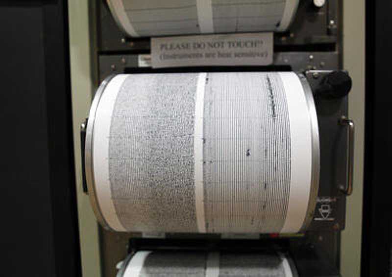
Recording onto Paper
|
|
Lyle Denny of Michigan constructed a seismic system based on
this web site.
Also discussed are: a) Data Acquisition, input analog voltage value into your computer b) Data Logging, showing and saving seismometer output on your computer. |
An amateur looks at professional needs and equipment - Jan 13, 2017
|
I am thinking of adding a section
"an amateur looks at professional needs and equipment" discussing that an amateur is happy to see that his/her equipment has "captured" an "event" from far away ::
But the professional is interested in more:
Missing from most (?all?) amateur reports is calibration data
(If you are looking for oil, with dynamite, your frequencies are higher and life is likely easier in this respect :-)) Of course you have other troubles --
Local earthquakes can easily sent these horizontal instruments we have been talking about
off their physical scale.
|
Toward Sensor Linearization
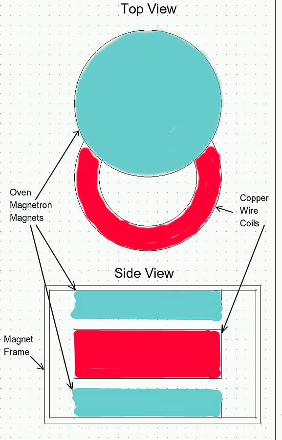
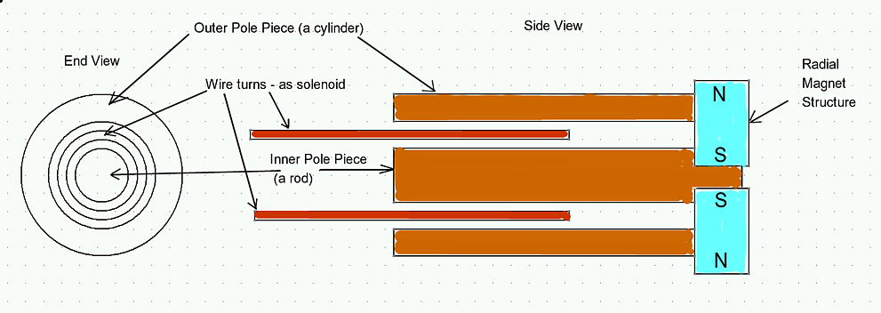 In the early 1970s I was allowed to closely examine a Sprengnether long period
horizontal seismograph. Other than solid beautiful construction, I noticed the
magnet and coil sensor. This roughly what I remember from 45 years ago.
(I'm guessing at the polarity of the radial magnet structure.)
In the early 1970s I was allowed to closely examine a Sprengnether long period
horizontal seismograph. Other than solid beautiful construction, I noticed the
magnet and coil sensor. This roughly what I remember from 45 years ago.
(I'm guessing at the polarity of the radial magnet structure.)
Guessing at the dimensions, I estimate 3 inches diameter, 5 inches long. I forget if the magnetic structure or the the wire wound solenoid was attached to the boom. I do remember the wire was a larger diameter than I expected - maybe #32 enameled wire. Note that for most of the travel of the solenoid in and out of the magnetic structure, you can expect a rather linear change of magnetic flux per millimeter of movement. I imagine that the pole pieces could be tapered to improve linearity.
 Most amateurs (certainly myself) did not try for this level of sensor linearity.
If using magnets, we tend to use circular magnets and circular coils and use an alignment similar to
the figure on the left. (click on the figures to enlarge)
Most amateurs (certainly myself) did not try for this level of sensor linearity.
If using magnets, we tend to use circular magnets and circular coils and use an alignment similar to
the figure on the left. (click on the figures to enlarge)
The equation (not including fringing effects) for the magnetic flux change through the coils per millimeter of offset from this position is unpleasant, but definitely non-linear. If we calibrate carefully with the components in say this position, and the components shift due to changes in leveling, then the calibration is no longer accurate. This limits the usefulness of our data for serious seismic work, such as velocity or displacement estimates.
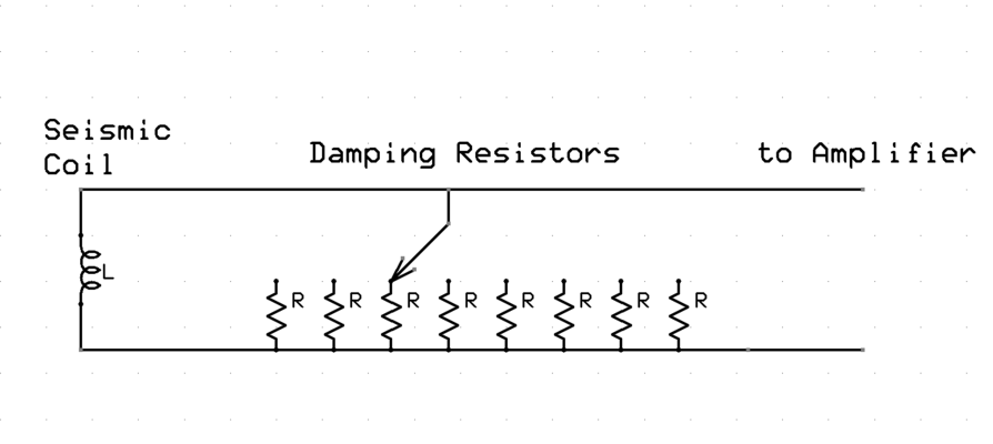
 However, lets make the coil narrow, with straight sides. A person would guess that the
elongated coil would provide quite good linearity (and relatively constant resistive damping)
over quite a range of positions. :-))
However, lets make the coil narrow, with straight sides. A person would guess that the
elongated coil would provide quite good linearity (and relatively constant resistive damping)
over quite a range of positions. :-))
(Next time ;-) |
Another Amateur Machine from Lyle Denny, Jan 30, 2017
|
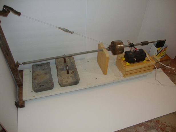
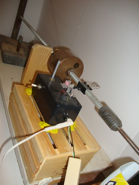
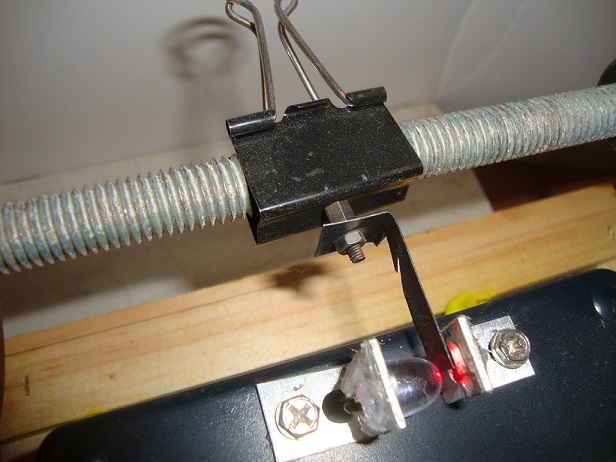
Mr. Thelen,
I thought you might like to see my home brew seismometer. So here is a series of photos. You can see the LED and photo cell arrangement. The graphic is of a 4.5 mag earthquake that occurred about 60 mile south(near Galesburg Mi) of my home on May 2, 2015. It was a classic wave form, you can see all the elements of the wave. The boom is suspended with a guitar string. I let the five pound mass hang on it for two weeks to get the stretch out of it. On the end of the boom I have a pan of mineral oil and a paddle for a damper. I have almost zero maintenance. Twice a year I take my laser level and check the boom for level and the offset of the pivot points to be sure I have 1mm offset. It is hard to get the offset as I use a ball bearing on a flat surface for the top pivot, but it works. I added 50 pounds of lead to the base to increase it's sensitivity and it did. The seismometer is in my old basement shower room away from drafts and other interferences, foot traffic. You can believe this or not but when someone walks around upstairs the house and foundation tip and this thing will detect it and when strong winds come along same thing will happen. I have been very satisfied with it's performance or the years. Thank you for putting up with me as there isn't many people that have this boring hobby. Regards
Lyle Denny
|


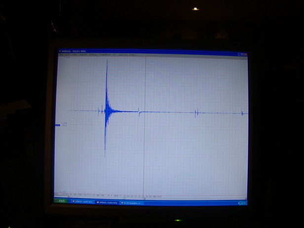
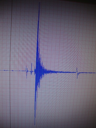
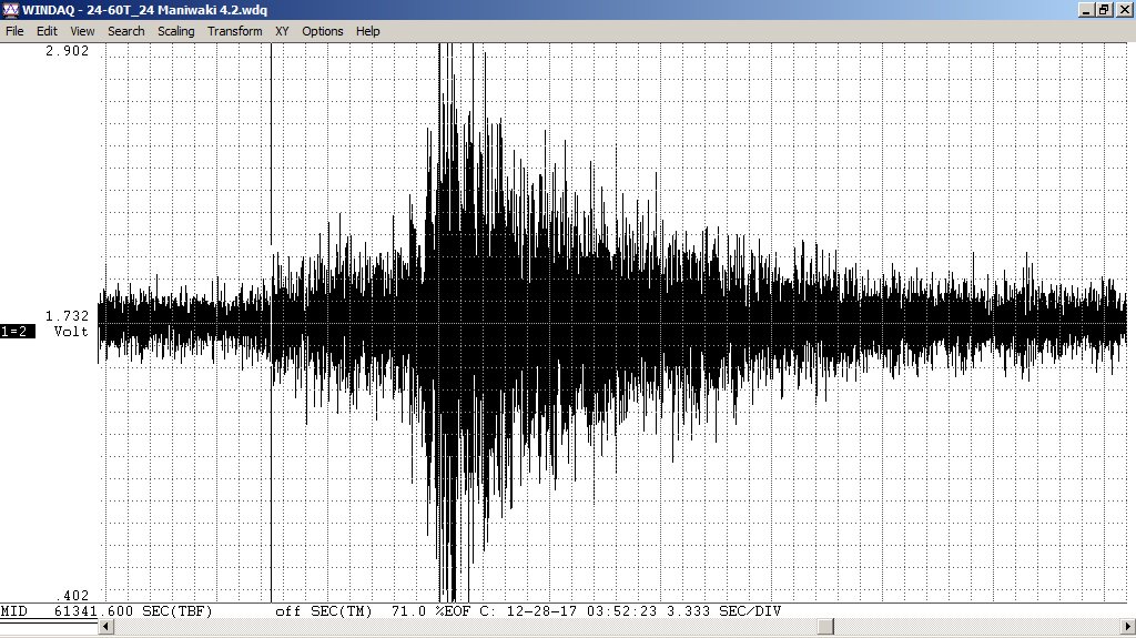
Wanted smaller, Marcel-Marie LeBel, April 15, 2018 < mlebel0314 @ rogers . com >
|
Ed,
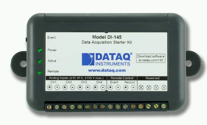
How are you? I am 63 and retired. Over the years I have tried spring and weight for seismograph.... magnets and coils etc. But I wanted smaller and more sensitive... So, I took a 2 inch piece of lab rubber tube, plugged at one end with bleeder hole and with an electret microphone capsule at the other end. The rubber tube provides spring and damping all in one. The end of a cylindrical 400 gr weight rests horizontally across on it. The signal is amplified with stereo preamp and then fed to a DI-145 Dataq data logger. I have been running this rig for now 3 years... There are a few problems with my station. One is the city noise. The other is baroms or infra-sound. The detector being a pressure sensor, I have to distinguish what is due to ground movement from infra-sounds . So I have a second tube and microphone without the weight that I record on a second channel. Attached is a trace for a 4.2 M earthquake 200 km away. (second channel removed) I wouldn't say boring.... But definitely the loneliest :-) Thanks,
Marcel,
|
amateur seismology community is very small, Alain Michaud, Nov 8, 2021 < info @ alainmichaud . ca >
|
Hi Mr. Thelen,
I am an amateur seismologist. Retired, I have been quite active for the last three years building a seismometer, and programming a web page. or just google: alainmichaud.ca Please feel free to have a look or even link to it. Sincerely Alain Michaud info@alainmichaud.ca p.s. I am not (yet) a member of the facebook seismology group. I find the amateur seismology community is very small. [ Ed Thelen here, I don't do facebook. ] |
Web page started Dec 10, 2012
updated Dec 2, 2018