Go To Table of Contents
| BRL 1964, HONEYWELL 400, starting page 0116
|
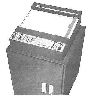
HONEYWELL 400
MANUFACTURER
Minneapolis-Honeywell Regulator Company
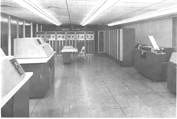 Photo by Minneapolis-Honeywell
APPLICATIONS
General purpose scientific and engineering computing. General purpose
business data processing. Real-time applications.
PROGRAMMING AND NUMERICAL SYSTEM
Internal number system Binary coded decimal
Binary digits/word 48 + 2 check bits
Decimal digits/word 12 + 2 check bits
or 11 + sign + 2 check bits
Alphanumeric chars/word 8 + 2 check bits
Binary digits/instruction 48
Instructions/word 1
Instructions decoded 63
Arithmetic system Fixed and floating point
Floating point is standard by sub-routine; optional by built-in hardware.
Fixed point is standard.
Instruction type Three address
Number range
48 binary digits, 12 decimal digits, 11 decimal digits + sign
Instruction word format
+---------+---------+-----------+-----------+
| 1 12 | 13 25 | 26 38 | 39 48 |
+---------+---------+-----------+-----------+
| Command | Address | B Address | C Address |
| Code | | | |
+---------+---------+-----------+-----------+
The command includes 6-bit operation code and 6-bit index register
designation.
Automatic built-in subroutines
Automatic subsequence on error conditions.
Extensive editing instructions.
Automatic coding
EASY-Assembly System
COBOL-Business Compiler
AUTOMATH-Scientific Compiler (FORTRAN II compatible)
Sort-Collate Routines
Scientific Library
Input/Output Package and Report Editor
PERT
Run Monitor
Photo by Minneapolis-Honeywell
APPLICATIONS
General purpose scientific and engineering computing. General purpose
business data processing. Real-time applications.
PROGRAMMING AND NUMERICAL SYSTEM
Internal number system Binary coded decimal
Binary digits/word 48 + 2 check bits
Decimal digits/word 12 + 2 check bits
or 11 + sign + 2 check bits
Alphanumeric chars/word 8 + 2 check bits
Binary digits/instruction 48
Instructions/word 1
Instructions decoded 63
Arithmetic system Fixed and floating point
Floating point is standard by sub-routine; optional by built-in hardware.
Fixed point is standard.
Instruction type Three address
Number range
48 binary digits, 12 decimal digits, 11 decimal digits + sign
Instruction word format
+---------+---------+-----------+-----------+
| 1 12 | 13 25 | 26 38 | 39 48 |
+---------+---------+-----------+-----------+
| Command | Address | B Address | C Address |
| Code | | | |
+---------+---------+-----------+-----------+
The command includes 6-bit operation code and 6-bit index register
designation.
Automatic built-in subroutines
Automatic subsequence on error conditions.
Extensive editing instructions.
Automatic coding
EASY-Assembly System
COBOL-Business Compiler
AUTOMATH-Scientific Compiler (FORTRAN II compatible)
Sort-Collate Routines
Scientific Library
Input/Output Package and Report Editor
PERT
Run Monitor
| BRL 1964, HONEYWELL 400, starting page 0117
|
Registers and B-Boxes
Three Index Registers are standard.

ARITHMETIC UNIT
                           Average Time Incl.
                           Stor. Access
                           Microsec
Fixed Decimal Add            111.0
Fixed Decimal Multiply     1,591.0
Fixed Decimal Divide       5,574.0
Fixed Binary Add             101.8

The above times are for the three-address operation
A + B -> C etc. (11 decimal digits, operands + sign
Arithmetic mode        Parallel
Timing                 Asynchronous
Operation              Sequential
  Tape read-write overlap
  Print run can be performed simultaneously with another program without
   special programming.
Simultaneous processing and program interrupt facilitate real time
   operation.

STORAGE
                  No. of       No. of    Access
Medium            Words        Digits    Microsec
 Magnetic Core     1,024       12,285     9.25
                to 4,096    to 49,152
Magnetic Disk             600,000,000 (Max) 1,180 (Avg)
Magnetic Tape
No. of units that can be connected        16 Units
No. of digits/linear inch              1,110 Digits/inch
Channels or tracks on the tape            10 Track/tape
Blank tape separating each record          0.66 Inches
Tape speed                               120 Inches/sec
Transfer rate decimal digits/sec     133,000 Digits/sec
Cross gap time                             5.55 Millisec
 Average time for experienced
operator to change reel of tape           20 Seconds
 Physical properties of tape
 Width                                     0.75 Inches
 Length of reel                        2,500 Feet
 Composition
    Mylar base with oxide coating.
Vacuum techniques used to mount reel, drive, stop and control tape.
Error detection and correction by orthotronic control.
Variable length records.
Other tape units operating at 48,000 and 96,000 decimal digits/second are
available.

INPUT
Medium             Speed          Remarks
Card Reader       800 cards/min   (Card buffer avail)
Paper Tape Reader 500 or
                1,000 frames/sec (5,6,7 or 8 channel
Ortho-scanner   1,500  doc/min
The scanner reads Honeywell ortho-bar code, rejection rate is less than
           0.1°%.
Optical-scanner   196, 240 or  312 doc/min Real-Time Input
Varies with circuit facilities on toll or leased wire circuits.

OUTPUT
Medium Speed
Card Punch        250 cards/min
Printer           900 lines/min
Paper Tape        110 frames/sec
Real-Time Output
Varies with circuit facilities on toll or leased wire circuits.
Buffered console keyboard and printer are standard. Simultaneous peripheral
processing. Program interrupt and priority processing.

CHECKING FEATURES
Fixed:
   Memory Parity (2 parity bits/word)
   Internal Logic
   Card Reader hole count and data validity.
   Card Punch hole count and data validity.
   Printer echo check and data validity.
   Magnetic Tape and disk orthotronic detection and correction.

POWER, SPACE, WEIGHT, AND SITE PREPARATION
Power, computer           24.2 KVA
Area, computer           700 sq ft
Floor loading             75 lbs/sq ft
Capacity, air conditioning 5 Tons
Site preparation requirements
      208 volt, 60 cycle, 3 phase power delivered through
      5 wire cable (4 wire + ground.
Raised floor recommended with 5 inch clearance.

COST, PRICE AND RENTAL RATES
                                     PURCHASE     RENTAL
TYPICAL SYSTEM                       PRICE        MONTH
Central Processor w/2,048 word/mem. $ 218,925    $ 4,865
4 Magnetic Tape Units                  81,000      1,130
High Speed Printer                     47,250      1,050
Card Reader-Punch                      30,215        550
                  TOTAL             $ 377,390    $ 8,265
ADDITIONAL EQUIPMENT
Additional Memory Blocks 1,024 words $ 29,250      $ 650
Multiply-Divide Option                 11,250        250
Print-Storage Option                   17,550        390
Rental price includes maintenance. Maintenance contract available for
purchased systems. Rates depend on age
of component, generally following decreasing scale.

PERSONNEL REQUIREMENTS
Varies with size of installation and applications.
Training made available by the manufacturer to the
user includes courses for executives, supervisors,
programmers and operators available to customers without cost.

RELIABILITY, OPERATING EXPERIENCE
Extensive built-in checking and special construction
techniques result in high reliability factor. System is modular
in construction designed for simplicity of maintenance
and replacement of parts.

ADDITIONAL FEATURES AND REMARKS
Outstanding features include unprogrammed transfers
automatically detect error conditions, orthotronic control
allows detection and correction of tape read errors,
program interrupt and priority processing are standard
features, adaptable to both scientific computation and
business data processing, large expansion possible and it
is compatible with Honeywell 1400.

The Honeywell 1400 is identical to the Honeywell 400
except that it is faster internally, and has a larger
expansion potential. Peripheral components in the
two systems are the same. Honeywell 400 users may switch
to the Honeywell 1400 without reprogramming.

PRODUCTION RECORD
First deliveries December 1963.
| BRL 1964, HONEYWELL 1400, starting page 0118
|
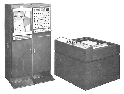
HONEYWELL 1400
MANUFACTURER
Minneapolis-Honeywell Regulator Company
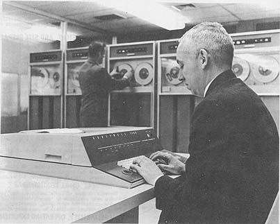 Photo by Minneapolis-Honeywell
APPLICATIONS
General purpose scientific and engineering computing. General purpose
business data processing. Real-time applications.
PROGRAMMING AND NUMERICAL SYSTEM
Internal number system Binary coded decimal
Binary digits/word 48 + 2 check bits
Decimal digits/word 12 + 2 check bits
or 11 + sign + 2 check bits
Alphanumeric chars/word 8 + 2 check bits
Binary digits/instruction 48
Instructions/word 1
Instructions decoded 73
Arithmetic system Fixed and floating point
Floating point is standard by sub-routine; optional by built-in hardware.
Fixed point is standard
Instruction type Three address
Number range
48 binary digits, 12 decimal digits, 11 decimal digits + sign
Floating point range 1051 to 10-49
Instruction word format
+---------+---------+-----------+-----------+
| 1 12 | 13 25 | 26 38 | 39 48 |
+---------+---------+-----------+-----------+
| Command | Address | B Address | C Address |
| Code | | | |
+---------+---------+-----------+-----------+
The command includes 6-bit operation code and 6-bit index register
designation.
Automatic built-in subroutines
Automatic subsequence on error conditions.
Extensive editing instructions.
Automatic coding
EASY-Assembly System
COBOL-Business Compiler
AUTOMATH-Scientific Compiler (FORTRAN II compatible)
Sort-Collate Routines
Scientific Library
Input/Output Package and Report Editor
PERT
Run Monitor
Photo by Minneapolis-Honeywell
APPLICATIONS
General purpose scientific and engineering computing. General purpose
business data processing. Real-time applications.
PROGRAMMING AND NUMERICAL SYSTEM
Internal number system Binary coded decimal
Binary digits/word 48 + 2 check bits
Decimal digits/word 12 + 2 check bits
or 11 + sign + 2 check bits
Alphanumeric chars/word 8 + 2 check bits
Binary digits/instruction 48
Instructions/word 1
Instructions decoded 73
Arithmetic system Fixed and floating point
Floating point is standard by sub-routine; optional by built-in hardware.
Fixed point is standard
Instruction type Three address
Number range
48 binary digits, 12 decimal digits, 11 decimal digits + sign
Floating point range 1051 to 10-49
Instruction word format
+---------+---------+-----------+-----------+
| 1 12 | 13 25 | 26 38 | 39 48 |
+---------+---------+-----------+-----------+
| Command | Address | B Address | C Address |
| Code | | | |
+---------+---------+-----------+-----------+
The command includes 6-bit operation code and 6-bit index register
designation.
Automatic built-in subroutines
Automatic subsequence on error conditions.
Extensive editing instructions.
Automatic coding
EASY-Assembly System
COBOL-Business Compiler
AUTOMATH-Scientific Compiler (FORTRAN II compatible)
Sort-Collate Routines
Scientific Library
Input/Output Package and Report Editor
PERT
Run Monitor
| BRL 1964, HONEYWELL 1400, starting page 0119
|
Registers and B-Boxes
Three Index Registers are standard.

ARITHMETIC UNIT
                  Average Time Incl.
                  Stor. Access Microsec
                  Fixed       Floating
Decimal Add          78.0        149.5
Decimal Multiply  1,118.0      1,085.5
Decimal Divide    3,386.5      2,801.5
Binary Add           71.5         - -
The above times are for the three-address operation
A + B -> C etc. (11 decimal digits, operands + sign)
Arithmetic mode          Parallel
Timing                   Asynchronous
Operation                Sequential
Tape read-write overlap.
Card reader-punch, and printer buffers available.
Print-run can be performed simultaneously with another
program without special programming.
Simultaneous processing and program interrupt facilitate
real-time operation.

STORAGE
                 No. of        No. of    Access
 Medium          Words         Digits    Microsec
 Magnetic Core     2,048       24,570         6.5
               to 32,768   to 393,216
Magnetic Disk (max)       600,000,000     1,180 (Avg)
Magnetic Tape
 No. of units that can be connected    16 Units
 No. of digits/linear inch          1,110 Digits/inch
 Channels or tracks on the tape        10 Track/tape
Blank tape separating each record       0.66 Inches
Tape speed 120 Inches/sec
Transfer rate decimal digits/sec  133,000 Digits/sec
 Cross gap time                         5.55 Millisec
 Average time for experienced
operator to change reel of tape        20 Seconds
 Physical properties of tape
 Width                                  0.75 Inches
 Length of reel                     2,500 Feet
 Composition
         Mylar base with oxide coating.
Vacuum techniques used to mount reel, drive, stop and control tape.
Error detection and correction by orthotronic control.
   Variable length records.
Other tape units operating at 48,000 and 96,000 decimal digits/second are
  available.

INPUT
 Medium            Speed           Remarks
Card Reader        800 cards/min    (Card buffer avail)
Paper Tape Reader  500 or           (5,6,7 or 8 channel
                 1,000 frames/sec
Ortho-scanner    1,500 doc/min
The scanner reads Honeywell ortho-bar code, rejection
rate is less than    0.1°%.
Optical-scanner    196, 240 or  312 doc/min Real-Time Input
Varies with circuit facilities on toll or leased wire circuits.

OUTPUT
Medium           Speed
Card Punch       250 cards/min
Printer          900 lines/min
Paper Tape       110 frames/sec
Real-Time Output
Varies with circuit facilities on toll or leased wire circuits.
Buffered console keyboard and printer are standard.
Simultaneous peripheral processing. Program interrupt and
priority processing.

CHECKING FEATURES
Fixed:
   Memory Parity (2 parity bits/word)
   Internal Logic
   Card Reader hole-count and data validity.
   Card Punch hole-count and data validity.
   Printer echo-check and data validity.
   Magnetic Tape and disk orthotronic detection
       and correction.

POWER, SPACE, WEIGHT, AND SITE PREPARATION
Power, computer      42.0 KVA
Area, computer      745 sq ft
Floor loading        75 lbs/sq ft
Capacity, air conditioning 8 Tons
Site preparation requirements
208 volt, 60 cycle, 3 phase power delivered through
5 wire cable (4 wire + ground).
Raised floor recommended with 5 inch clearance.

COST, PRICE AND RENTAL RATES
TYPICAL SYSTEM PURCHASE MON/RENTAL
Central Processor w/4,096 word/mem.    $ 330,750   $ 7,350
6 Magnetic Tape Units                    121,500     2,700
High Speed Printer                        47,250     1,050
Card Reader-Punch                         30,215       550
                                 TOTAL $ 529,715   $11,650

ADDITIONAL EQUIPMENT
Additional Memory Blocks 4,096 words    $ 72,000   $ 1,600
Card Storage Option                       22,050       490
Print Storage Option                      17,550       390
Multi-Channel Communic. control           42,300       940
Floating Point Option                      6,750       150
Multiply-Divide Option                    11,250       250
Rental price includes maintenance. Maintenance contract available
for purchased systems. Rates depend on age of component, generally
following decreasing scale.

PERSONNEL REQUIREMENTS
Varies with size of installation and applications. Training
made available by the manufacturer to the user includes
courses for executives, supervisors, programmers and operators
available to customers without cost.

RELIABILITY, OPERATING EXPERIENCE
Extensive built-in checking and special construction techniques
result in high reliability factor. System is modular
in construction designed for simplicity of maintenance and
replacement of parts.

ADDITIONAL FEATURES AND REMARKS
Outstanding features include unprogrammed transfers automatically
detect error conditions, orthotronic control
allows detection and correction of tape read errors, program
interrupt and priority processing are standard
features, adaptable to both scientific computation and
business data processing, large expansion possible and it
is compatible with Honeywell 400.

The Honeywell 1400 is identical to the Honeywell 400
except that it is faster internally, and has a larger
expansion potential. Peripheral components in the two
 systems are the same.
Honeywell 400 users many switch to the Honeywell 1400
without reprogramming.

PRODUCTION RECORD
First deliveries December 1963.
| BRL 1964, HONEYWELL 1800, starting page 0120
|
HONEYWELL 1800
MANUFACTURER
Minneapolis-Honeywell Regulator Co., EDP Div.

APPLICATIONS
General purpose scientific and engineering, (including
real-time), and general purpose business applications.

PROGRAMMING AND NUMERICAL SYSTEM
Internal number system Binary coded decimal
Binary digits/word               48 (+ 6 check digits)
Binary digits/instruction        48
Instructions/word                 1
Instructions decoded             63 basic types
Arithmetic system                Fixed & floating point
Floating point is standard by library routine and
optional by automatic floating-point unit.
Instruction type                 Three address
Number Range
Decimal: 10-65 up to 1063
 Binary: 10-78 up to 1077
Instruction word format
+---------+-----------+-----------+-----------+
| 1    12 | 13     24 | 25     36 | 37     48 |
+---------+-----------+-----------+-----------+
| Command | A Address | B Address | C Address |
| Code*   |           |           |           |
+---------+-----------+-----------+-----------+
* Variously interpreted depending on instruction type.
Automatic built-in subroutines
  Read/Write Error
  Begin/End Tape
  Parity Failure
  Exponential Overflow/Underflow
  Addition/Subtraction Overflow
  Division Overcapacity
Automatic coding
  Automatic routine generating and updating system.
  Fully automatic compiling technique (FACT).
  Automath(FORTRAN-IV compatible).
  Common business oriented language (COBOL).
  Computer organization package (COP) - includes
    executive routine,
    comprehensive file of systems programs,
    sorts, library of subroutines and macroroutines.
Registers and B-Boxes
Eight groups of 32 registers each--total of 256
special registers. Each group has 2 arithmetic control
registers, 4 sequence/history registers, 1 unprogrammed
transfer register, 1 mask index register, 8 index registers,
4 input-output/general purpose registers,
and 12 general purpose registers.
There are also an accumulator and low-order product register;
a floating accumulator and floating loworder
product register, a floating auxiliary register; a mask register;
a program control register, and a machine control register.

ARITHMETIC UNIT
(Includes scientific option 1801-B)
          Incl. Stor. Access
          Microsec
Add            8
Mult          12
Div           22
 Above times are for floating point operations.
Vacuum-Tubes         0
Transistors      3,000
Diodes          15,000 Arithmetic mode
Parallel - Serial - Parallel
Timing               Synchronous
Operation            Concurrent
Automatic parallel processing is entirely controlled by
two interrelated logical elements which allow up to eight
independent programs to proceed simultaneously:
   1. Traffic Control directs the time sharing of main memory
     cycles by sixteen input/output trunks and the central processor;
   2. Multiprogram Control directs the time sharing of the central
     processor by eight independent program control centers.

 STORAGE
                             No. of     Access
 Medium           Words      Digits     Microsec
Magnetic Core     32,768     393,216        2
(Main Memory)
Magnetic Core        256       1,024        2
(Control Memory)
Magnetic Disk  5,625,000  67,500,000  129,000
The magnetic core time given above is actually the cycle time,
and includes access and regeneration time.
Magnetic Tape
 No. of units that can be connected     64 Units
 No. of chars/linear inch            1,554 Chars/inch
 Channels or tracks on the tape         10 Track/tape
 Blank tape separating each record       0.67 Inches
 Tape speed                            120 Inches/sec
Transfer rate                      133,000 or 186,000 Dec. dig/sec
 Start time                              3.5 Millisec
 Stop time                               3.5 Millisec
 Average time for experienced
operator to change reel of tape         20 Seconds
 Physical properties of tape
 Width                                   0.75 Inches
 Length of reel                      2,500 Feet + 50 ft
Composition Mylar base with oxide coating
Magnetic tape with a transfer rate of 133,000 dec chars/second
is also available.
A vacuum is used to seat reels on hubs, to maintain loops
in loop chambers, and to provide contact with capstans.

INPUT
Medium             Speed
Punched Card     240 cards/min
Punched Card     650 cards/min
Punched Card     800 cards/min
Paper Tape       500/1,000 frames/sec
Optical Scanning 312 doc/min
Magnetic Ink   1,160 doc/min
Magnetic Disk  1,160 doc/min
The communications control unit allows receipt and
transmission of data over toll or leased-wire circuits.
For real-time operations, control units and interfaces are supplied.

OUTPUT
Medium             Speed
Printer          150/900 lines/min
Punched Card     100/250 cards/min
Paper Tape       110 frames/sec
Magnetic Disk
| BRL 1964, HONEYWELL 1800, starting page 0121
|
CIRCUIT ELEMENTS OF ENTIRE SYSTEM
Type Quantity Remarks
Tubes 0
Diodes 60,000 Excl. peripheral equipment
Transistors 12,000 Excl. peripheral equipment
CHECKING FEATURES
Accuracy assured through extensive internal checking,
verification of all data transmission, arithmetic processes,
address modification, memory selections, and control processing.
Orthotronic Control provides automatic error detection and
correction for magnetic tape and other input/output media.
POWER, SPACE, WEIGHT, AND SITE PREPARATION
Power, computer 35 Kw 65 KVA 0.80 pf
(Typical system)
Air conditioner (Customer-supplied).
Area, data processing 1,580 sq ft
Area, service eng. 300 sq ft
Floor loading 75 lbs/sq ft
Capacity, air conditioner 13 Tons
Weight, computer 15,720 lbs
Site preparation requirements
Usual power requirements are for a source supplying
208 volts, 60-cycle, 3-phase, 4-wire, plus equipment ground.
Raised floors are used: A step-high floor with at least 5 1/2 inches
clearance above the true floor has been found satisfactory.
Ceiling height: 8 feet.
COST, PRICE AND RENTAL RATES
MONTHLY PURCHASE
D E S C R I P T I 0 N RENTAL PRICE
Central Processor (8,000 memory) $ 32,950 $1,585,200
Tape Control & 8 Units Card Reader/Punch Hi-Speed
Printer ) & Control
Additional Equipment:
1 Additional. memory block (8,000) 3,200 153,600
Floating Point Option 4,300 206,400
Training made available by the manufacturer to the user
includes training programs for executives, supervisors,
programmers and operators - without charge and tailored
to the needs of the user.
RELIABILITY, OPERATING EXPERIENCE
Each unit of entire system incorporates fail-safe checking.
Special construction techniques minimize cold-solder joints and
intermittent contacts.
All units are designed for simplicity of maintenance
and rapid replacement of parts.
ADDITIONAL FEATURES AND REMARKS
Outstanding features include high speed and flexibility.
Easily adapted to business or scientific problems - or to a
wide variety of special purpose activity (e.g., real-time, military,
information retrieval). Powerful proven software package.
Parallel processing, orthotronic control, floating point,
and nanosecond speed.
The system is compatible with Honeywell 800. There is a
wide choice of input/output equipment.
Relative humidity in the computer area should be held at
approximately 40°% to insure optimum tape performance.
Dry bulb temperature should not exceed 74oF;
wet bulb temperature should not exceed 59oF.
PRODUCTION RECORD
Time required for delivery 12 to 15 months
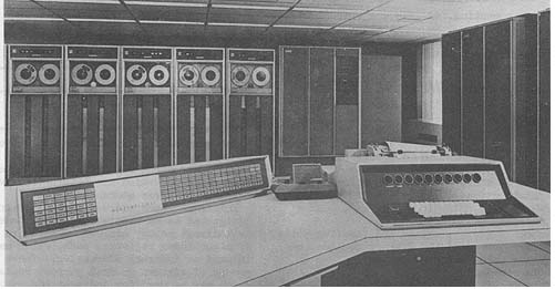 Photo by Minneapolis-Honeywell
| BRL 1964, HONEYWELL 1800-II, starting page 0122
|
HONEYWELL 1800 II
MANUFACTURER
Minneapolis-Honeywell Regulator Company
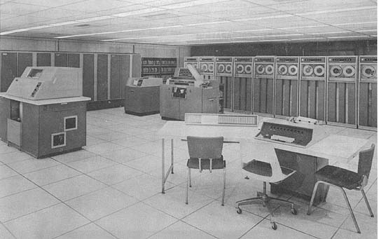 Photo by Minneapolis-Honeywell
APPLICATIONS
General purpose computing, on-line and real-time uses.
General purpose scientific and engineering computing.
General purpose business data processing and control
of real-time physical systems.
PROGRAMMING AND NUMERICAL SYSTEM
Internal number system Binary coded decimal
Binary digits/word 48 (+ 6 check digits)
Binary digits/instruction 48
Instructions/word 1
Instructions decoded 63 basic types
Arithmetic system Fixed & floating point
Floating point is standard by library routine and
optional by automatic floating-point unit.
Instruction type Three address
Number Range
Decimal: 10-65 up to 1063
Binary: 10-78 up to 1077
Instruction word format
+---------+-----------+-----------+-----------+
| 1 12 | 13 24 | 25 36 | 37 48 |
+---------+-----------+-----------+-----------+
| Command | A Address | B Address | C Address |
| Code | | | |
+---------+-----------+-----------+-----------+
The command code interpretation varies, depending on instruction type.
The instruction word is divided logically into four sections,
which are interpreted as a command code followed by three addresses.
Indexing. Each address in an instruction may be designated as an absolute
address, indexed address, or indirect memory address. There are
eight groups of eight index registers each, which may be used for
indexed or indirect addressing. There are also eight groups of
sixteen general purpose registers each, which may be used for indirect
addressing. An increment, which is automatically added to these registers,
can be indicated in an instruction.
Photo by Minneapolis-Honeywell
APPLICATIONS
General purpose computing, on-line and real-time uses.
General purpose scientific and engineering computing.
General purpose business data processing and control
of real-time physical systems.
PROGRAMMING AND NUMERICAL SYSTEM
Internal number system Binary coded decimal
Binary digits/word 48 (+ 6 check digits)
Binary digits/instruction 48
Instructions/word 1
Instructions decoded 63 basic types
Arithmetic system Fixed & floating point
Floating point is standard by library routine and
optional by automatic floating-point unit.
Instruction type Three address
Number Range
Decimal: 10-65 up to 1063
Binary: 10-78 up to 1077
Instruction word format
+---------+-----------+-----------+-----------+
| 1 12 | 13 24 | 25 36 | 37 48 |
+---------+-----------+-----------+-----------+
| Command | A Address | B Address | C Address |
| Code | | | |
+---------+-----------+-----------+-----------+
The command code interpretation varies, depending on instruction type.
The instruction word is divided logically into four sections,
which are interpreted as a command code followed by three addresses.
Indexing. Each address in an instruction may be designated as an absolute
address, indexed address, or indirect memory address. There are
eight groups of eight index registers each, which may be used for
indexed or indirect addressing. There are also eight groups of
sixteen general purpose registers each, which may be used for indirect
addressing. An increment, which is automatically added to these registers,
can be indicated in an instruction.
| BRL 1964, HONEYWELL 1800-II, starting page 0123
|
Masking. The ability to mask words allows most internal processing
instructions in the Honeywell 1800 Il to work with fields of
variable length. Each program may designate a group of up to
96 memory locations as masking registers. Such a designation
may be changed by the programmer at any point in his program.
Thus, an essentially unlimited number of masking registers is
at his disposal.
Automatic built-in subroutines
  Read/Write Error Detection
  Begin End Tape
  Parity Failure
  Exponential Overflow/Underflow
  Addition/Subtraction Overflow
  Division Overcapacity
Automatic subsequencing to specified memory location.
Automatic coding
ARGUS - Automatic Routine Generating and Updating  System;
         Assembly System
FACT -Fully Automatic Compiling Technique;
Business Compiler COBOL - Common Business Oriented Language;
          Business Compiler
AUTOMATH - FORTRAN IV compatible;
          Scientific  Compiler
COP - Computer Optimization Package; includes
 executive routine, sort-collate routines,
 input/output routine, library of sub-routines
 and macro-routines, program test system.
ADMIRAL - Dynamic multiprogram operating system.

Registers and B-Boxes
Eight groups of 32 registers each - total 256 special registers.
Each group includes two Arithmetic Control Counters,
Sequence Counter, Consequence Counter, Sequence History Register,
Consequence History Register, Unprogrammed Transfer Register,
Mask Index Register, eight Index Registers and sixteen General Purpose
Registers.

The H-1800 and H-1800 II also includes: Accumulator and low-order product
register; floating accumulator and floating low-order product register;
floating auxiliary register; mask register, program control register,
 machine control register.

ARITHMETIC UNIT
                   Average Time Incl.
                   Stor. Access
 Microsec
Fixed Decimal Add          8
Fixed Decimal Multiply    54
Fixed Decimal Divide      44
Floating Binary Add       10
Floating Binary Multiply  10
Floating Binary Divide    28
The above times (include scientific floating point 1801B) are for the
three-address operation A + B - C etc. (11 decimal digits, operands + sign)
Construction (Arithmetic unit only)
Vacuum Tubes            0
 Transistors        3,000
 Diodes            15,000
Arithmetic mode        Parallel-Serial-Parallel
Timing                 Synchronous Operation
Automatic parallel processing allows eight independent programs
to proceed simultaneously. This feature is hardware controlled and
requires no special programming or master monitor routine.
Traffic Control directs the time sharing of main memory cycles by 16
input/output trunks and the central processor.
Multiprogram Control directs the time sharing of the central processor by 8
independent program control centers.
The H-1800 and H-1800-II, are identical except that the H-1800-II includes
an Input/Output Control Center. This IOCC requires one input and an output
trunk and is capable of controlling one card reader, one card punch, one
high-speed printer and four magnetic tape units. All of these peripheral
units may be operated simultaneously, either on-line with the central
processor or off-line, in any combination of operations. Any combination
of peripheral units and their control units may be connected to the
remaining trunks.
Complete buffering allows Read/Write/Compute overlap.

STORAGE
 No. of No. of Access
Medium Words Digits Microsec
 Magnetic Core (Main) 65,536(Max)786,432 2
Access time includes access and restoration.
Magnetic Core (Control) 256 (16-bits) 1,024 2
Access time includes access and restoration. Magnetic Disk 100, 663, 000
(Max) 1,207,957,000(Max)
 *129,000 (Avg) microseconds
Magnetic Tape
 No. of units that can be connected 64 Units
 No. of decimal digits/linear inch 1,550 Dig/inch
 Channels or tracks on the tape 10 Track/tape
 Blank tape separating each record 0.67 Inches
 Tape speed 120 Inches/sec
 Transfer rate decimal digits 186,000 Dig/sec
 Start time 2.7 Millisec
 Stop time 3.5 Millisec
 Average time for experienced
operator to change reel of tape 20 Seconds
 Physical properties of tape
 Width 0.75 Inch
 Length of reel 2,500 Feet
 Composition
 Mylar base with oxide coating.
Other magnetic tape units available with transfer rates of 48,000; 96,000;
133,000 decimal digits/sec.
Vacuum control used to seat reels on hubs to maintain loops in chambers,
and to provide contact with capstans.
Rewind speed 360 inches/second.
INPUT
Medium Speed Card Reader
Punched Card 240 cards/min Standard Speed
 650 cards/min High Speed
 800 cards/min Punch
Paper Tape 500 frames/sec (5,6,7, or 8 level codes)
 1,000 frames/sec
Optical Scanning 312 doc/min (Max)
Magnetic Ink 1,160 doc/min (Max)
OUTPUT
Medium Speed Remarks
Printer 150 lines/min 120 position
 900 lines/min 120160 position
Punched Card 100 cards/min Standard Speed Punch
 250 cards/min Card Reader/Punch
Paper Tapes 110 frames/sec
Communications Control Unit allows H-1800-II to receive and transmit data
over toll or leased wire circuits.
For real-time operations, real-time control units and interfaces are
supplied.
| BRL 1964, HONEYWELL 1800-II, starting page 0124
|
CHECKING FEATURES
Accuracy assured through extensive checking of all internal and peripheral
operation; verification of all data
transfers, arithmetic operations; address modifications, memory selections
and control processing. Orthotronic
control provides detection and correction of tape read errors.

POWER, SPACE, WEIGHT, AND SITE PREPARATION
Power, computer typical system     71.7 KVA 80,% pf
Area, data processing           1,580 sq ft
Area, service engineer            300 sq ft
Floor loading                      75 lbs/sq ft
Capacity, air conditioner          13 Tons
Weight, computer               15,720 lbs
Site preparation requirements
Power source supplying 208 volts, 60 cycle, 3 phase, 4-wire plus equipment
ground.
Air conditioner supplied by customer.
Raised floor with at least 5.5 inch clearance is recommended.
Ceiling height: 8 feet
Relative humidity in area should be held at approximately 45 /o to insure
optimum tape performance. Dry bulb-
wet bulb temperature should not exceed 74oF-59 F.

PRODUCTION RECORD
Time required for delivery 12 months

PERSONNEL REQUIREMENTS
Typical personnel requirement varies widely depending upon size of
installation and applications.
Training made available by the manufacturer to the user includes complete
executive, supervisor, programming,
operating courses at no cost to the customer.

RELIABILITY, OPERATING EXPERIENCE
Each unit of entire system incorporates fail-safe checking, special
construction, techniques eliminate cold-solder
joints and intermittent contacts. All units are modular in construction,
designed for simplicity of maintenance and
rapid replacement of parts.

ADDITIONAL FEATURES AND REMARKS
Exceptional speed and flexibility. Equally efficient with scientific or
business applications. Ability to run 8
programs in parallel and control a large number of peripheral, real time,
and communications devices add to its
flexibility. Extensive checking including orthotronic control for
correction of tape errors are standard features.
Unique system advantages include compatibility with Honeywell 800, and a
wide variety of peripheral devices
and parallel processing.

COST, PRICE AND RENTAL RATES
TYPICAL SYSTEM DESCRIPTION                  PURCHASE     MONTHLY
 PRICE RENTAL
Central Processor with 8,192 word memory    $ 858,000    $ 18,000
Tape Control Unit                              96,000       2,000
8 Magnetic Tape Units (96,000 cycles/sec)     345,600       7,200
High-Speed Printer                             74,400       1,550
Card Reader-Punch                              30,000         550
                                            ---------     -------
                                           $1,404,000    $ 29,300

ADDITIONAL EQUIPMENT
Floating Point Option                       $ 206,400     $ 4,300
Additional Memory Blocks (8,192 words)        153,600       3,200
| BRL 1964, HONEYWELL 1800-II, starting page 0125
|
| BRL 1964, HUGHES HCM 101, starting page 0126
|
HUGHES HCM 101
MANUFACTURER
Hughes Aircraft Company

APPLICATIONS
Aircraft fire control, navigation, system test, etc. The system is based on
the LRI-X System, and was developed for the AN/ASG-18 Fire Control System.

PROGRAMMING AND NUMERICAL SYSTEM
Internal number system          Binary
Binary digits/word               21
Binary digits/instruction        21
Instructions/word                 1
Arithmetic system                Fixed point
Instruction type                 One address
Number range                     +- 218
Instruction word format          Variable
Automatic coding
An assembler has been prepared. Registers and B-Boxes
There are 16 fast-access (4 word) registers.
Variable length multiply and divide features are available.

ARITHMETIC UNIT
                  Excl. Stor. Access
                      Microsec
Add                      80
Mult                     40/bit
Div                      40/bit
Construction (Arithmetic unit only)  Silicon transistors are used.
Arithmetic mode          Serial
Timing                   Synchronous
Operation                Sequential

STORAGE
                No. of        No. of Binary     Access
   Medium       Words         Digits/Word       Microsec
Magnetic Drum     62,000      21                12,500(avg)

INPUT
                        No. of Lines
                        Medium Available
AC Analog Lines         24
DC Analog Lines         40
Incremental Lines        4
Digital Lines          120

 OUTPUT
                       No. of Lines
 Medium Available
DC Lines                 32
Servo Lines              20
Incremental Lines         3
Digital Lines             6

CIRCUIT ELEMENTS OF ENTIRE SYSTEM
All silicon semiconductors are used.

CHECKING FEATURES
A built-in automatic self-test routine is run, with fault isolation to
identify a faulty circuit card.

POWER, SPACE, WEIGHT, AND SITE PREPARATION
Power, computer       0.57 Kw
Volume, computer      4 cu ft
Weight, computer    164 lbs
| BRL 1964, HUGHES HCM 121, starting page 0127
|
    HUGHES HCM 121
    Command Guidance Computer

    MANUFACTURER
    Hughes Aircraft Company


    Photo by Hughes Aircraft Company

    APPLICATIONS
    Space probe guidance and control. The system is used in connection with
    the Atlantic Missile Range.

    PROGRAMMING AND NUMERICAL SYSTEM
    Internal number system     Binary
    Binary digits/word         26
    Binary digits/instruction  13
    Instructions/word           2
    Arithmetic system          Floating point
    Instruction type           One address
    Number range               +- 223
    Instruction word format    Variable

    ARITHMETIC UNIT
                Excl. Stor. Access  Microsec
    Add          95
    Mult         48
    Div          48
    Operation times are per bit.
    Construction (Arithmetic unit only)
       Transistors
    Arithmetic mode   Serial
    Timing            Synchronous
    Operation         Sequential

    STORAGE
                     No. of      No. of Binary      Access
         Medium      Words       Digits/Word        Microsec
    Drum             5,280          13              5,700

    INPUT AND OUTPUT
    Digital for both.

    POWER, SPACE, WEIGHT, AND SITE PREPARATION
    Power, computer        0.170 Kw
    Volume, computer       2.3 cu ft
    Weight, computer      85 lbs

     PRODUCTION RECORD
    Number produced to date      14
    Time required for delivery    8 months
Photo by Hughes Aircraft Company
APPLICATIONS
Space probe guidance and control. The system is used in connection with
the Atlantic Missile Range.
PROGRAMMING AND NUMERICAL SYSTEM
Internal number system Binary
Binary digits/word 26
Binary digits/instruction 13
Instructions/word 2
Arithmetic system Floating point
Instruction type One address
Number range +- 223
Instruction word format Variable
ARITHMETIC UNIT
Excl. Stor. Access Microsec
Add 95
Mult 48
Div 48
Operation times are per bit.
Construction (Arithmetic unit only)
Transistors
Arithmetic mode Serial
Timing Synchronous
Operation Sequential
STORAGE
No. of No. of Binary Access
Medium Words Digits/Word Microsec
Drum 5,280 13 5,700
INPUT AND OUTPUT
Digital for both.
POWER, SPACE, WEIGHT, AND SITE PREPARATION
Power, computer 0.170 Kw
Volume, computer 2.3 cu ft
Weight, computer 85 lbs
PRODUCTION RECORD
Number produced to date 14
Time required for delivery 8 months
| BRL 1964, HUGHES HCM 122, starting page 0128
|
    HUGHES HCM 122
    Surveillance Data Analyzer

    MANUFACTURER
    Hughes Aircraft Company


    Photo by the Hughes Aircraft Company

    APPLICATIONS
    The AN/UVS-l Target Locating System for use with the unmanned drone.

    PROGRAMMING AND NUMERICAL SYSTEM
    Internal number system      Binary
    Binary digits/word          26
    Binary digits/instruction   13
    Instructions/word            2
    Arithmetic system           Fixed point
    Instruction type            One address
    Number range                +- 223
    Instruction word format     Variable

    ARITHMETIC UNIT
                     Excl. Stor. Access
                      Microsec
    Add               88
    Mult              44/bit
    Div               44/bit
    Construction (Arithmetic unit only)
       Transistors
    Arithmetic mode   Serial
    Timing            Synchronous
    Operation         Sequential

    STORAGE
                            No. of Binary    Access
                No. of      Digits/Word      Microsec
    Drum        5,760        26              5,700

    INPUT AND OUTPUT
    Analog and Digital

    POWER, SPACE, WEIGHT, AND SITE. PREPARATION
    Power, computer     0.17 Kw
    Volume, computer    2.3 cu ft
    Weight, computer   85 lbs

     PRODUCTION RECORD
    Number produced to date     4
    Time required for delivery  9 months
Photo by the Hughes Aircraft Company
APPLICATIONS
The AN/UVS-l Target Locating System for use with the unmanned drone.
PROGRAMMING AND NUMERICAL SYSTEM
Internal number system Binary
Binary digits/word 26
Binary digits/instruction 13
Instructions/word 2
Arithmetic system Fixed point
Instruction type One address
Number range +- 223
Instruction word format Variable
ARITHMETIC UNIT
Excl. Stor. Access
Microsec
Add 88
Mult 44/bit
Div 44/bit
Construction (Arithmetic unit only)
Transistors
Arithmetic mode Serial
Timing Synchronous
Operation Sequential
STORAGE
No. of Binary Access
No. of Digits/Word Microsec
Drum 5,760 26 5,700
INPUT AND OUTPUT
Analog and Digital
POWER, SPACE, WEIGHT, AND SITE. PREPARATION
Power, computer 0.17 Kw
Volume, computer 2.3 cu ft
Weight, computer 85 lbs
PRODUCTION RECORD
Number produced to date 4
Time required for delivery 9 months
| BRL 1964, HUGHES HCM 301, starting page 0129
|
    HUGHES HCM 301

    MANUFACTURER
    Hughes Aircraft Company


    Photo by Hughes Aircraft Company

    APPLICATIONS
    The system is a digital differential analyzer used .
    for ballistic missile guidance.

    PROGRAMMING AND NUMERICAL SYSTEM
    Internal number system      Binary
    Binary digits/word          17
    Binary digits/instruction   17
    Instructions/word            1
    Arithmetic system           Fixed point
    Instruction type            Sequential wired program.
    Number range                +- 216

    ARITHMETIC UNIT
    The arithmetic unit performs 800 iterations/second.
    Construction (Arithmetic unit only)
    The arithmetic unit consists of transistors,
        diodes, and magnetic cores.
    Arithmetic mode       Series - parallel
    Timing                Synchronous
    Operation             Sequential

     STORAGE
                                   No. of    No. of Binary
     Medium                        Words     Digits/Word
    Magnetic Core Shift Register    11       17
Photo by Hughes Aircraft Company
APPLICATIONS
The system is a digital differential analyzer used .
for ballistic missile guidance.
PROGRAMMING AND NUMERICAL SYSTEM
Internal number system Binary
Binary digits/word 17
Binary digits/instruction 17
Instructions/word 1
Arithmetic system Fixed point
Instruction type Sequential wired program.
Number range +- 216
ARITHMETIC UNIT
The arithmetic unit performs 800 iterations/second.
Construction (Arithmetic unit only)
The arithmetic unit consists of transistors,
diodes, and magnetic cores.
Arithmetic mode Series - parallel
Timing Synchronous
Operation Sequential
STORAGE
No. of No. of Binary
Medium Words Digits/Word
Magnetic Core Shift Register 11 17
| BRL 1964, HUGHES HCM 201, starting page 0130
|
    HUGHES HCM 201

    MANUFACTURER
    Hughes Aircraft Company


    Photo by Hughes Aircraft Company

    APPLICATIONS
    Guidance and Control, navigation of Aerospace vehicles.
    It is designed for operation in military
    environments. It can be installed in missiles, satellites,
    aircraft, ship or vans.

    PROGRAMMING AND NUMERICAL SYSTEM
    Internal number system     Binary
    Binary digits/word         24
    Binary digits/instruction  12
    Instructions/word           2
    Instructions decoded       30
    Instruction type           One address
    Instruction word format    Variable
     Depending on type of instruction.
    Automatic coding
       An assembler is being developed.
    Registers and B-Boxes
       8 Index Registers

    ARITHMETIC UNIT
                  Incl. Stor. Access   Excl. Stor. Access
                  Microsec             Microsec
    Add             6                    6
    Mult          120                  120
    Div           120                  120
    Construction (Arithmetic unit only)
     Vacuum-Tubes     0
     Transistors    829
     Diodes       2,951
     Magnetic Cores
         Depends on size of memory.
    Arithmetic mode    Parallel
    Timing             Synchronous
    Operation          Sequential

    STORAGE
                      No. of      No. of Binary     Access
    Medium            Words       Digits/Word       Microsec
    Magnetic Core     16,000       24                6
     (Transfluxor)
    Magnetic Core      4,000       24                6
    Magnetic Drum  1,500,000
     (Gas Bearing)
    Magnetic Tape
       No. of units that can be connected    0 Units
    INPUT
     Medium Analog (AC & DC)
     Digital
     Discrete
Photo by Hughes Aircraft Company
APPLICATIONS
Guidance and Control, navigation of Aerospace vehicles.
It is designed for operation in military
environments. It can be installed in missiles, satellites,
aircraft, ship or vans.
PROGRAMMING AND NUMERICAL SYSTEM
Internal number system Binary
Binary digits/word 24
Binary digits/instruction 12
Instructions/word 2
Instructions decoded 30
Instruction type One address
Instruction word format Variable
Depending on type of instruction.
Automatic coding
An assembler is being developed.
Registers and B-Boxes
8 Index Registers
ARITHMETIC UNIT
Incl. Stor. Access Excl. Stor. Access
Microsec Microsec
Add 6 6
Mult 120 120
Div 120 120
Construction (Arithmetic unit only)
Vacuum-Tubes 0
Transistors 829
Diodes 2,951
Magnetic Cores
Depends on size of memory.
Arithmetic mode Parallel
Timing Synchronous
Operation Sequential
STORAGE
No. of No. of Binary Access
Medium Words Digits/Word Microsec
Magnetic Core 16,000 24 6
(Transfluxor)
Magnetic Core 4,000 24 6
Magnetic Drum 1,500,000
(Gas Bearing)
Magnetic Tape
No. of units that can be connected 0 Units
INPUT
Medium Analog (AC & DC)
Digital
Discrete
| BRL 1964, HUGHES HCM 201, starting page 0131
|
    OUTPUT
     Medium Analog (DC)
     Digital
     Servomechanism

    CIRCUIT ELEMENTS OF ENTIRE SYSTEM
     Type          Quantity
    Tubes               0
    Diodes          7,000
    Transistors     2,000
    All silicon semiconductors are used.

    CHECKING FEATURES
    The system has a complete self-test capability
    with fault isolation routines.

    POWER, SPACE, WEIGHT, AND SITE PREPARATION
    Power, computer       0.150 Kw 28 Volt DC
    Weight, computer     51 lbs
    An air conditioner is not required.

    PRODUCTION RECORD
    Number produced to date        1
    Number in current operation    1
    Number in current production  10
    Time required for delivery     6 months
| BRL 1964, HUGHES HW 15K, starting page 0132
|
HW 15K
MANUFACTURER
H-W-Electronics, Inc.
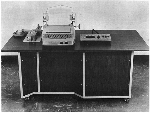 Photo by H-W-Electronics, Inc.
APPLICATIONS
Engineering office and small business office applications.
The computer may be adopted to any specific application
within the scope of the machine's capability.
For example, an on-line application where a customer his
several sets of input data which must be
scanned in sequence or in parallel and then operated upon.
This, of course will dictate additional buffer
registers which can then be used for other routines.
The IN-15K general purpose computer is a machine
capable of the payroll, inventory, and editing
function in a business application, and of the mathematical
routines of the engineering office. The HW-15K may also
serve as a rack-mounted version in special situations or
on-line applications in industry, or
as a satellite computer in a large computer installation.
PROGRAMMING AND NUMERICAL SYSTEM
Internal number system Binary
Binary digits/word 24
Instructions/word 1
Instructions decoded 12
Arithmetic system Fixed point
Instruction type One address
Number range +- (223- 1) or 8,388,607
Instruction word format
+-------+------+--------+---------+--------+
| 1 6 | 7 10 | 11 12 | 13 17 | 18 24 |
+-------+------+--------+---------+--------+
| Spare | OP | I/0 | Track | Word |
+-------+------+--------+---------+--------+
| | Code | | Address |
+-------+------+--------+------------------+
Address
Registers and B-Boxes
Accumulater Register (AC)
Instruction Counter (IC)
Action Register (AR)
ARITHMETIC UNIT
Incl. Stor. Access
Microsec
Add 650
Arithmetic mode Serial
The basic pulse repetition rate is 192,000 cycles/sec
Timing Synchronous
Operation Concurrent
Photo by H-W-Electronics, Inc.
APPLICATIONS
Engineering office and small business office applications.
The computer may be adopted to any specific application
within the scope of the machine's capability.
For example, an on-line application where a customer his
several sets of input data which must be
scanned in sequence or in parallel and then operated upon.
This, of course will dictate additional buffer
registers which can then be used for other routines.
The IN-15K general purpose computer is a machine
capable of the payroll, inventory, and editing
function in a business application, and of the mathematical
routines of the engineering office. The HW-15K may also
serve as a rack-mounted version in special situations or
on-line applications in industry, or
as a satellite computer in a large computer installation.
PROGRAMMING AND NUMERICAL SYSTEM
Internal number system Binary
Binary digits/word 24
Instructions/word 1
Instructions decoded 12
Arithmetic system Fixed point
Instruction type One address
Number range +- (223- 1) or 8,388,607
Instruction word format
+-------+------+--------+---------+--------+
| 1 6 | 7 10 | 11 12 | 13 17 | 18 24 |
+-------+------+--------+---------+--------+
| Spare | OP | I/0 | Track | Word |
+-------+------+--------+---------+--------+
| | Code | | Address |
+-------+------+--------+------------------+
Address
Registers and B-Boxes
Accumulater Register (AC)
Instruction Counter (IC)
Action Register (AR)
ARITHMETIC UNIT
Incl. Stor. Access
Microsec
Add 650
Arithmetic mode Serial
The basic pulse repetition rate is 192,000 cycles/sec
Timing Synchronous
Operation Concurrent
| BRL 1964, HUGHES HW 15K, starting page 0133
|
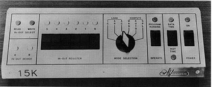 Photo by H-W-Electronics, Inc.
Processing concurrent with Input/output operations.
STORAGE
No. of No. of Bin.
Medium Words Digits/Word
Magnetic Drum 4,096 24
The drum rotates at 3,600 revolutions/minute. The
capacity may be increased.
INPUT
Medium Speed
Paper Tape 20 chars/sec
Keyboard (IBM Selectric) Manual
OUTPUT
Medium Speed
Paper Tape 20 chars/sec
Typewriter (IBM Selectric) 15 chars/sec
CIRCUIT ELEMENTS OF ENTIRE SYSTEM
Solid-state circuit elements are used; transistors,
crystal diodes, and printed circuits.
CHECKING FEATURES
Parity is checked when transferring out of storage.
POWER, SPACE, WEIGHT, AND SITE PREPARATION
Power, computer 0.8 Kw 1.0 KVA
Volume, computer 64 in x 30 in.x 31 1/2 in.
Site preparation requirements
105 - 125 volts, 60 cycle/sec power.
Air conditioning is not required.
COST, PRICE AND RENTAL RATES
Computer, with 4,096-word magnetic drum, paper tape input-output,
and typewriter is less than $20,000.00.
ADDITIONAL FEATURES AND REMARKS
Constructed of standard tested and proved modules
manufactured by H-W-Electronics for many years. It
was a logical step to assemble these modules into
two 19-inch relay-rack assemblies, attach the storage
drum and input-output equipment, and fit the packages
into a desk.
OPERATION CODE,.
BINARY INSTRUCTION EFFECT
0000 - HLT Halt
0001 - NOP No Operation
0010 - TRA Transfer
0011 - TRN Transfer if AC negative
Ol00XX RDE Read
0101XX WTE Write
0110 - SHR Shift Right
0111 - CYR Cycle Right
1000 - CLA Clear and Add
1001 - spare
1010 - ADD Add
1011 - SUB Subtract
1100 - STO Store
1101 - spare
1110 - spare
1111 - spare
    Photo by H-W-Electronics, Inc.

    Processing concurrent with Input/output operations.

    STORAGE
                       No. of     No. of Bin.
     Medium            Words      Digits/Word
     Magnetic Drum      4,096        24
    The drum rotates at 3,600 revolutions/minute. The
    capacity may be increased.

     INPUT
       Medium                     Speed
    Paper Tape                     20 chars/sec
    Keyboard (IBM Selectric)       Manual

    OUTPUT
    Medium                        Speed
    Paper Tape                     20 chars/sec
    Typewriter (IBM Selectric)     15 chars/sec

    CIRCUIT ELEMENTS OF ENTIRE SYSTEM
    Solid-state circuit elements are used; transistors,
    crystal diodes, and printed circuits.

    CHECKING FEATURES
    Parity is checked when transferring out of storage.

    POWER, SPACE, WEIGHT, AND SITE PREPARATION
    Power, computer       0.8 Kw 1.0 KVA
    Volume, computer     64 in x 30 in.x 31 1/2 in.
    Site preparation requirements
     105 - 125 volts, 60 cycle/sec power.
     Air conditioning is not required.

    COST, PRICE AND RENTAL RATES
    Computer, with 4,096-word magnetic drum, paper tape input-output,
     and typewriter is less than   $20,000.00.

    ADDITIONAL FEATURES AND REMARKS
    Constructed of standard tested and proved modules
    manufactured by H-W-Electronics for many years. It
    was a logical step to assemble these modules into
    two 19-inch relay-rack assemblies, attach the storage
    drum and input-output equipment, and fit the packages
    into a desk.

     OPERATION CODE,.
     BINARY INSTRUCTION EFFECT
     0000 - HLT Halt
     0001 - NOP No Operation
     0010 - TRA Transfer
     0011 - TRN Transfer if AC negative
     Ol00XX RDE Read
     0101XX WTE Write
     0110 - SHR Shift Right
     0111 - CYR Cycle Right
     1000 - CLA Clear and Add
     1001 - spare
     1010 - ADD Add
     1011 - SUB Subtract
     1100 - STO Store
     1101 - spare
     1110 - spare
     1111 - spare
| BRL 1964, HYDAC 2000, starting page 0134
|
HYDAC 2000
Hybrid Digital Analog Computer
MANUFACTURER
Electronics Associates, Inc.
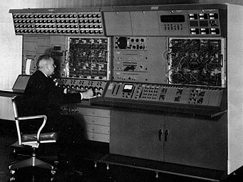 Photo by Electronics Associates, Inc.
APPLICATIONS
The HYDAC, Series 2000, is a general-purpose,
hybrid analog and digital computing system providing
automatic operation of the high-speed analog computing
capacility to permit iterative and sequential
computation for a broad class of problems in many
fields of engineering. The logic, memory, conversion
and input-output features extend the use of analog
computing techniques into new fields such as data
processing and statistical analysis. The digital system
is also very effective as a simulator of digital
controllers which may be used in conjunction with a
dynamic simulation of the physical system on the
analog console.
The HYDAC 2000 is composed of a general-purpose
analog computing console with a special control patch
panel and a digital console composed of logic elements,
memory units, analog-to-digital and digital-to-
analog converters, plus a paper tape input-output
system. To provide the parallel operation required for
compatibility with the analog computer, the digital
elements terminate on a removable patch-panel
similar to the analog console. This approach allows
multiple channels of logical control and memory to
communicate with the analog system simultaneously
at very high speed. Analog computer portion is
PACE 2318 V. Digital Operations System is DOS 350.
PROGRAMMING AND NUMERICAL SYSTEM
Internal number system Binary
Binary digits/word 16
Arithmetic system Fixed point
Multiple parallel, adding-subtracting units.
Photo by Electronics Associates, Inc.
APPLICATIONS
The HYDAC, Series 2000, is a general-purpose,
hybrid analog and digital computing system providing
automatic operation of the high-speed analog computing
capacility to permit iterative and sequential
computation for a broad class of problems in many
fields of engineering. The logic, memory, conversion
and input-output features extend the use of analog
computing techniques into new fields such as data
processing and statistical analysis. The digital system
is also very effective as a simulator of digital
controllers which may be used in conjunction with a
dynamic simulation of the physical system on the
analog console.
The HYDAC 2000 is composed of a general-purpose
analog computing console with a special control patch
panel and a digital console composed of logic elements,
memory units, analog-to-digital and digital-to-
analog converters, plus a paper tape input-output
system. To provide the parallel operation required for
compatibility with the analog computer, the digital
elements terminate on a removable patch-panel
similar to the analog console. This approach allows
multiple channels of logical control and memory to
communicate with the analog system simultaneously
at very high speed. Analog computer portion is
PACE 2318 V. Digital Operations System is DOS 350.
PROGRAMMING AND NUMERICAL SYSTEM
Internal number system Binary
Binary digits/word 16
Arithmetic system Fixed point
Multiple parallel, adding-subtracting units.
| BRL 1964, HYDAC 2000, starting page 0135
|
    Automatic built-in subroutines.

    A variety of subroutine programs have been written for
    memory operations, and input-output. Routines
    for performing various arithmetic operations such
    as multiplication and resolution have also been
    prepared. These sub-routines are patched on the
    removable, storable panels of the digital console.

    Although the HYDAC 2000 system is not designed to
    provide conventional stored program capability,
    arithmetic units are provided to supplement the
    mathematical capability of the analog system. This
    capability is used both in a time-shared fashion
    to reduce the use of analog elements as well as
    a convenient means of performing simple arithmetic
    operations in conjunction with other digital
    programs such as function generation.

    ARITHMETIC UNIT
               Excl. Stor. Access
                Microsec
    Add          8
    Mult       128
    Arithmetic mode         Serial
    Timing                  Synchronous
    Operation               Concurrent

    STORAGE
                       No. of     No. of Binary     Access
    Medium             Words      Digits/Word       Microsec
    Magnetostrictive    3,082     16 bits           8 sequential
     Delay Lines                                    2 random

    INPUT
     Medium            Speed
     Paper Tape        500 - 1,000 chars/sec
    Bi-directional reader with spooler for 500 chars second.

    OUTPUT
     Medium                Speed
     Paper Tape             110 chars/sec
    Tape is spooled on compatible reels

    CIRCUIT ELEMENTS OF ENTIRE SYSTEM
     Type      Quantity
    Tubes
     6072          200
     6U8           125
     6AW8          125
     7719          250
                  ----
     Total         700

    Diodes
     ED1871A    12,000
     CTP462      1,000
     CR5488      1,600
     ED6008      1,000
                ------
     Total      15,600

    Transistors
     SM291       5,000
     SM423         800
     2N404         400
     2N964         300
     2N2276        150
     2N797         100
     2N1308        100
     2N324         200
                 -----
     Total       7,050

    Magnetic Cores   0
    Other diodes, transistors and tubes comprise
    insignificant percentage of total.

    CHECKING FEATURES
    Neon indicators for all flip-flops with associated
    Manual Set-Reset Control.

    Logic and Signal Selector (Addressable selection of
    all Logic or Analog Elements without Fixed-Readout

    Voltage Monitor Panel (Meters all system voltages

    Static Test. Rate Test and Initial Derivatives test
    for analog components.

    Amplifier Overload Indicator.
    Reduced Clock and Manual Clock provisions for DOS 350.

    POWER, SPACE, WEIGHT, AND SITE PREPARATION
    Power, computer              8 KVA
    Power, air conditioner       4 KVA
    Volume, computer           300 cu ft
    Area, computer              65 sq ft
    Floor loading, computer    110 lbs/sq ft
    Volume, air conditioner     35 cu ft
    Area, air conditioner       10 sq ft
    Capacity, air conditioner    5 Tons
    Weight, computer         7,000 lbs
    Weight, air conditioner  1,000 lbs
    Site preparation requirements
    Depends on site but usually only air conditioning
     is necessary for the analog portion.

    PERSONNEL REQUIREMENTS
                 One 8-Hour Two 8-Hour
                 Shift      Shifts
    Analysts      2            2
    Programmers   2            3
    Technicians   1            2
    Training is made available by the manufacturer
    to the user including a 1 week maintenance course,
    a 1 week operator/programmer course, and an advanced
    application course of 1 and 2 weeks.

    RELIABILITY, OPERATING EXPERIENCE
    I DOS 350 - Digital Operations System
    Basic circuit units in the system are high quality,
    ultra-reliable digital basic building blocks (potted,
    welded modules. These modules are mounted on plugin,
    etched circuit boards, which, in general, are
    housed in plug-in, logic building blocks. For this
    reason, with a minimum number of spares, faulty units
    may be quickly replaced and repairs made as work
    load permits, without incurring costly computer
    down-time.

    II PACE 2318 V - General Purpose Analog-Computer
    Performance-proven design with basic concepts and
    operating experience since 1953. Plug-in,
    removable chassis concept produces same results
    as cited above for DOS 350.

    ADDITIONAL FEATURES AND REMARKS
    Permits simulating complex, dynamic systems requiring
    both analog facilities and digital logic and
    memory in one, integrated system.

    Series 3110-3120-3130 Dataplotter, 11" x 17" Digital
    X-Y Plotter, Punched Card or Tape Input.
    On-line capability: Research-engineering, statistics,
    production, meteorogogical monitoring, telemetry,
    and map making.
| BRL 1964, HYDAC 2000, starting page 0136
|
    MODEL 3130 EAI DATAPLOTTER SPECIFICATIONS

    Data Input

    PUNCHED CARDS: Read with modified IBM 407, 513, 514, 517,
    519, 523, 024, 026 and 526 Summary Punches. The standard
    IBM Card of 80 columns and 12 rows is used.

    PUNCHED PAPER TAPE: Read with a modified Friden,
    Model 2, motorized tape reader. Accepts BCD code
    in serial form on 5, 7 and 8 level tape.

    KEYBOARD: Manually operated. Other inputs available on special order.

    Data Output

    POINT PLOT: Maximum useable plotting surface of
    10" x 15". Scale factor and parallax controls allow the
    plotting of a graph on any portion of the plotting surface.

    CODED SYMBOLS: Semi-Automatic Symbol Printer available
    as accessory. Up to 6 distinct symbols.

    Plotting Speed
    PUNCHED CARDS: Up to 100 points per minute.
    PAPER TAPE: Up to 120 points per minute.
    LINE: Up to 70 per minute.

    Plotting Accuracy
    VARIPLOTTER: Static Accuracy - 0.075% of full scale
    for pen and arm.

    CONVERSION: less than 0.1%.
    Physical Description
     Height             35 inches
     Width  . .         22 inches
     Weight (Uncrated) 203 Ibs. (Punched Card Input)
     Weight  , .       225 Ibs. (Card and tape Input)
     Depth              26 inches
     Power             115 volts, 100 watts


    Dataplotter 3110              Photo by Electronics Associates, Inc.
| BRL 1964, HYDAC 2000, starting page 0137
|
 Dataplotter 3120 Photo by Electronics Associates, Inc.
HYDAC 200 - Series 3440 Dataplotter, 30" x 30" Digital X-Y
Plotter, Magnetic Tape, Punched Card or Tape Input
Weather Charts
Mapping
Missile Tracking
Test Simulation
Statistics
Fully buffered.
Dataplotter series 3440 is designed to provide fast accurate
graphic recording of digital data from a variety of inputs.
Operates from magnetic tape, punched cards, papertape or keyboard.
    Dataplotter 3120       Photo by Electronics Associates, Inc.

    HYDAC 200 - Series 3440 Dataplotter, 30" x 30" Digital X-Y
    Plotter, Magnetic Tape, Punched Card or Tape Input
      Weather Charts
      Mapping
      Missile Tracking
      Test Simulation
      Statistics
      Fully buffered.

    Dataplotter series 3440 is designed to provide fast accurate
    graphic recording of digital data from a variety of inputs.

    Operates from magnetic tape, punched cards, papertape or keyboard.
| BRL 1964, HYDAC 2000, starting page 0138
|
 Dataplotter 3440 Photo by Electronics Associates, Inc.
MODEL 3440 EAI DATAPLOTTER
DATA INPUT
Magnetic Tape: Accepts 1 inch wide, 7 track, BCD tape,
written at a density of 200 characters per inch.**
Punched Cards: Read with parallel or serial fed Card Readers.
Punched Tape: High speed photo-electric reader capable
of reading tape with up to 8 levels.
Keyboard: Manually operated-adding machine type.
DATA OUTPUT*
Point Plot: Any size paper up to 30 inch x 30 inch
(available in plain or ruled sheets or rolls)
Continuous Line: Any size reproducible ink drawing on
any size paper up to 30 inch x 30 inch.
Coded Plots: Symbols-up to 12 distinct symbols (average
selection time 0.33 seconds) ; Numeric point identification.
PLOTTING ACCURACY (quoted as maximum errors)
Analog Plotter: 0.015 inches
Data Conversion: within 4 counts
Line Segment Conformity: 0.015 inches
PHYSICAL DESCRIPTION
Tape Reader and
Console X-Y Plotter
Width (overall) 42" 46"
Depth (overall) 32" 46 1/2"
Height 75 1/4" 41 1/2"
Weight (uncrated) 1212 lbs. 660 lbs.
Power-Requires 30 amp, 115V, 60 cycle (single phase)
service. (50 cycle model available on special order)
PLOTTING SPEEDS
Point Plots: Magnetic Tape (at 1/8 inch spacing) at least
350 ppm
Punched Cards:
Serial-fed-nominally 75 ppm
Parallel-fed-nominally 100 ppm
Punched Tape- nominally 300 ppm
Line Plot: Magnetic Tape: (depends upon setting of
Max. Point Displacement switch)
1/8 inch-540 lines/min
1/4 inch-306 lines/min
1/2 inch-144 lines/min
1 inch-114 lines/min
2 inch- 90 lines /min
5 inch- 42 lines/min
Punched Cards
Serial-fed-maximum 75 lines/min
Parallel-fed-maximum 100 lines/min
Punched Tape
maximum 300 lines/min
Coded Plots (1/2 inch spacing):
Magnetic Tape-at least 180 ppm
Punched Cards
Serial-fed-75 ppm
Parallel-fed-100 ppm
Punched Tape-180 ppm
Free Running Mode-up to 4500 ppm
(Data points are read at 75 inches per second
tape speed without stopping in the record gaps)
* Wide line (up to 1/16 inch) pens are available
** Other formats available on special order
(All equipment specifications contained herein are subject to change)
    Dataplotter 3440             Photo by Electronics Associates, Inc.

    MODEL 3440 EAI DATAPLOTTER

    DATA INPUT
    Magnetic Tape: Accepts 1 inch wide, 7 track, BCD tape,
     written at a density of 200 characters per inch.**
    Punched Cards: Read with parallel or serial fed Card Readers.
    Punched Tape: High speed photo-electric reader capable
      of reading tape with up to 8 levels.
    Keyboard: Manually operated-adding machine type.

    DATA OUTPUT*
    Point Plot: Any size paper up to 30 inch x 30 inch
     (available in plain or ruled sheets or rolls)
    Continuous Line: Any size reproducible ink drawing on
     any size paper up to 30 inch x 30 inch.
    Coded Plots: Symbols-up to 12 distinct symbols (average
     selection time 0.33 seconds) ; Numeric point identification.

    PLOTTING ACCURACY (quoted as maximum errors)
      Analog Plotter: 0.015 inches
      Data Conversion: within 4 counts
      Line Segment Conformity: 0.015 inches

    PHYSICAL DESCRIPTION
                        Tape Reader and
                        Console              X-Y Plotter
    Width (overall)     42"                  46"
    Depth (overall)     32"                  46 1/2"
    Height              75 1/4"              41 1/2"
    Weight (uncrated) 1212 lbs.             660 lbs.
    Power-Requires 30 amp, 115V, 60 cycle (single phase)
    service. (50 cycle model available on special order)

    PLOTTING SPEEDS
    Point Plots: Magnetic Tape (at 1/8 inch spacing) at least
         350 ppm
         Punched Cards:
           Serial-fed-nominally 75 ppm
           Parallel-fed-nominally 100 ppm
           Punched Tape- nominally 300 ppm
    Line Plot: Magnetic Tape: (depends upon setting of
       Max. Point Displacement switch)
          1/8 inch-540 lines/min
          1/4 inch-306 lines/min
          1/2 inch-144 lines/min
          1   inch-114 lines/min
    2 inch- 90 lines /min
    5 inch- 42 lines/min

    Punched Cards
        Serial-fed-maximum 75 lines/min
        Parallel-fed-maximum 100 lines/min

    Punched Tape
       maximum 300 lines/min
    Coded Plots (1/2 inch spacing):
          Magnetic Tape-at least 180 ppm
          Punched Cards
             Serial-fed-75 ppm
             Parallel-fed-100 ppm
          Punched Tape-180 ppm
    Free Running Mode-up to 4500 ppm
    (Data points are read at 75 inches per second
     tape speed without stopping in the record gaps)

    *  Wide line (up to 1/16 inch) pens are available
    ** Other formats available on special order

    (All equipment specifications contained herein are  subject to change)
| BRL 1964, HYDAC 2000, starting page 0139
|
ACCURACY AND RELIABILITY
The accuracy of the analog plotter is 0.015 inches;
conversion of the digital data is within 4 counts,
giving an overall plotting precision very close to
the width of the line drawn. High stability, wirewound
resistors and silicon diodes are located in a
thermostatically controlled oven to give extra protection
against changes in environmental temperature.
Analog operational amplifiers are chopper stabilized
and, except for the tape transport unit, all circuitry
is transistorized for greater reliability.
20,000 COUNT INPUT DATA RANGE
The DATAPLOTTER plots up to 4-digit decimal numbers
of either sign, making its range effectively 20,000
counts or +9999 to -9999. Front panel controls are
provided to permit plotting 1, 2, 3, or 4 digit numbers
as desired. Scale and origin controls allow the plot
to be compressed or expanded from 1/3 of full scale
to more than 10 times full scale and to move the data
origin to a point either on or off the plotting
surface up to 4 board widths, depending on the scale used.
THREE PLOTTING MODES
Two types of plots may be made with the standard
DATAPLOTTER: (a) Point Plots in which each set of X-Y
coordinates are recorded as a point, and (b) Line
Plots in which successive X-Y points are connected by
straight lines. As an optional feature the system
may be supplied with equipment to provide Symbol
Plots, either as one of 12 automatically selected
symbols or with numeric identification of points. The
VARIPLOTTER may also be equipped with a second
plotting arm for additional plotting versatility. When
the second arm is equipped with a symbol printer
both pen or symbol plots can be obtained by the
selection of the proper arm.
PARITY CHECK
Lateral parity check is maintained on selected
words to minimize the chances of error when data is
being plotted from magnetic tape. By placing the
Parity Action switch on the Control Panel in the
"Reject" position, the DATAPLOTTER automatically
rejects questionable data and continues plotting. With
this switch in the "Stop" position, faulty data
causes the DATAPLOTTER to cease all operations so that the
operator can examine the nature of the error and take
appropriate action. The operator may decide to
manually reject the data or to correct it by entering
correct information with the Manual Data Entry
Keyboard. After either of these actions are taken,
the plotter will continue to plot subsequent data.
MAINTENANCE
Trouble-shooting and maintenance are easily
accomplished on the Series 3440 DATAPLOTTER.
All triggers and counters in the system are monitored
by visual indicators. The keyboard may be used to
simulate the tape. In this mode all data detection,
control and counting circuitry are utilized. All
digital logic and control printed circuit cards are mounted
on rolling drawers for easy accessibility. Each of these
cards has color-coded phone jacks on its edge which
allow safe monitoring of the output of all active
elements on the card. In addition, a Test Panel is
provided which contains a selector switch for
monitoring any of the system power supplies with a self-
contained voltmeter, and balance potentiometers for
balancing the operational amplifiers.
OPTIONAL EQUIPMENT
Optional equipment is available for increasing the
plotting versatility of the Series 3440 DATAPLOTTER. This
includes printing facilities for symbol or numeric
identification of plotted data, automatic incremental
advance, paper roll mechanism and others.
SPECIAL MODELS
Variations of the Series 3440 DATAPLOTTER can be
provided on special order to accept magnetic tapes
from other digital computers. A VARIPLOTTER with a
45" x 58" plotting surface is also available on special
order.
Magnetic Tape Format Definitions
Character-consists of a group of bits placed in each
of the seven channels on the tape.
Record-a sequence of characters along the tape.
File-a sequence of records along the tape.
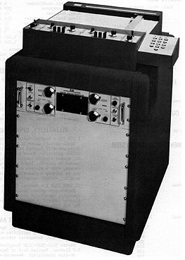
DIGITAL TAPE TRANSPORT
The tape transport used with the 3440 DATAPLOTTER
is the Ampex FR400, which is designed for reading
tape prepared by IBM 650, 704, 705, 709, 7070, 7090,
1401, 1620, and CDC 160 and 1604 Computers. It is
equipped with hubs for mounting standard IBM or NARTB
tape reels using % inch wide tape. The tape is
read at a speed of 75 inches per second with a seven-channel
reading head to fit the dimensions of the
recorded data. Manual controls are provided for controlling
the tape reader in addition to the
automatic controls that are required to carry out the automatic
plotting operations. Brakes are provided
to automatically stop the tape in event of tape breakage or
failure of AC power. Optionally available
are stop devices which sense the IBM end of the tape foil markers.
WORD & CHAR. SELECTION. A record is first divided into
words of arbitrary size (from 2 to 12 characters)
and the words into characters. The size of the word is
set on the Word Size dial. The location of the words
to be plotted within the record are set on the X and Y
Word Selector dials. Any word from 000 to 159 can
be selected. When plotting from magnetic tape, punched
tape or serially fed punched cards it is
possible to select the following characters from anywhere
within the desired word: sign character,
command character, thousands digit, hundreds digit,
tens digit, and units digit. These selections are
accomplished by the use of six dials for X and six for Y.
The action taken on each record will depend
upon the command characters which appear in the location
as set on the Command Character dials.
Note that it is possible to set the Command Character
selector to "0" in which case every X and Y word
selected will be plotted.
| BRL 1964, HYDAC 2000, starting page 0140
|
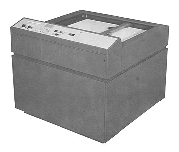 Series 5500 Data Plotter Photo by Electronics Associates, Inc.
It is a 30" Y 30" Digital X-Y Plotter with punched
card or tape input. The plotter has on-line capability, and
is used for research-engineering, statistics, production
highway planning, meteorological monitoring,
telemetry and map making.
The Dataplotter 5500 Series is designed to provide fast,
accurate graphic recording of digital data, with
fully-buffered input.
The system accepts a variety of input devices.
The circuitry is all solid-state construction.
The dimensions are:
Width - 46" Height - 41 3/4"
Depth - 46 1/8" Weight - 660 lbs
Training made available by the manufacturer to the user
includes complete operator and maintenance training.
In order to maximize reliability, it has chopper
stabalised operational amplifiers, hermetically
sealed reed relays, and a linear feedback mandrel.
Outstanding - features include:
High-Speed
One-Line Operation
Fully Buffered
Simplified Controls
Automatic Input-Command Selection
Variable Scale Factors
Line-Length Selection.
Point-Line or Symbol Printing is possible. The
plotting accuracy is 0.015 inches and the plotting
speed is 350 points/minute.
Research investigations and design calculations
performed by a digital computer can be plotted
accurately and economically in graphic form for
the rapid evaluation and comparison of results.
The Dataplotter 3500 System produces statistical
graphs quickly, economically and accurately to improve
the basis for business decision-making.
In the automatic programming of machine tools,
the Series 3500 Dataplotter System can be used to
check the sequencing and accuracy of input cards
or tape. Accurate and reliable, it is a quick,
convenient way to eliminate errors before machining operations.
In the design of a highway, cut and fill crosssectional
graphs are prepared at regular intervals, and as
many as 100/mile of road depending on topography. Complete
cross-sectional drawings for a typical
mile of rural highway design -- a costly, time consuming
task -- can be plotted in 30 minutes with the
Dataplotter Series 3500 System.
    Series 5500 Data Plotter    Photo by Electronics Associates, Inc.

    It is a 30" Y 30" Digital X-Y Plotter with punched
    card or tape input. The plotter has on-line capability, and
    is used for research-engineering, statistics, production
    highway planning, meteorological monitoring,
    telemetry and map making.

    The Dataplotter 5500 Series is designed to provide fast,
    accurate graphic recording of digital data, with
    fully-buffered input.

    The system accepts a variety of input devices.
    The circuitry is all solid-state construction.
    The dimensions are:
        Width - 46"        Height - 41 3/4"
        Depth - 46 1/8"    Weight - 660 lbs
    Training made available by the manufacturer to the user
    includes complete operator and maintenance training.

     In order to maximize reliability, it has chopper
     stabalised operational amplifiers, hermetically
     sealed reed relays, and a linear feedback mandrel.

    Outstanding - features include:
      High-Speed
      One-Line Operation
      Fully Buffered
      Simplified Controls
      Automatic Input-Command Selection
      Variable Scale Factors
      Line-Length Selection.

    Point-Line or Symbol Printing is possible. The
    plotting accuracy is 0.015 inches and the plotting
    speed is 350 points/minute.

    Research investigations and design calculations
    performed by a digital computer can be plotted
    accurately and economically in graphic form for
    the rapid evaluation and comparison of results.
    The Dataplotter 3500 System produces statistical
    graphs quickly, economically and accurately to improve
    the basis for business decision-making.

    In the automatic programming of machine tools,
    the Series 3500 Dataplotter System can be used to
    check the sequencing and accuracy of input cards
    or tape. Accurate and reliable, it is a quick,
    convenient way to eliminate errors before machining operations.

    In the design of a highway, cut and fill crosssectional
    graphs are prepared at regular intervals, and as
    many as 100/mile of road depending on topography. Complete
    cross-sectional drawings for a typical
    mile of rural highway design -- a costly, time consuming
    task -- can be plotted in 30 minutes with the
    Dataplotter Series 3500 System.
| BRL 1964, HYDAC 2000, starting page 0141
|
    Present day defense and space development programs
    require many elaborate and complex test
    facilities such as missile ranges, wind tunnels,
    and meteorological monitoring stations. Telemetered data
    from these facilities are produced in large quantities.
    Missile trajectories and space vehicle orbits,
    determined through digital computations, can be converted
    automatically to convenient graphic form.

    This system can be a valuable tool in reducing all such data to
    graphic form for faster, easier correlation and study.
    Contour lines and physical characteristics can be
    plotted manually by keyboard or automatically with
    the Dataplotter 3500 System.
    A complete software program package will be available by September 1964.

    FEATURES
- high speed
- solid state reliability
- simplified control panel
- on-line operation capability
- plots accurate graphs up to 30 x 30 inches as standard, 45 x 60 inch
graphs optional
- fully buffered input
- self-contained digital keyboard
- vacuum hold-down system for paper
- pin-point orientation lights for accurate paper alignment
- automatic input-command selection
- output mode selection
- variable scale factors and origin
offsets
- patch panel for axis assignment of scale
factor and origin controls
- line-length selection on input
command
- automatic switching from line to point or symbol
plotting
- incremental-advance plotting*
- 16 or 48 character symbolic, numeric, or alphanumeric point identification*
- manual or automatic paper roll mechanism*
- automatic scale factor and origin selection up to maximum of 20 controls*
*Optional
| BRL 1964, HYDAC 2400, starting page 0142
|
    HYDAC 2400
    Hybrid Digital-Analog Computer

    MANUFACTURER
    Electronic Associates, Inc.

    APPLICATIONS
    The HYDAC Series 2400 is a general-purpose,
    combined hybrid, digital-analog-computing-system
    providing automatic operation of the high-speed
    analog computing capability to permit iterative and
    sequential computation for a broad class of problems
    in many fields of engineering. This system is a
    particularly powerful tool for aerospace problems
    where the high accuracy requirements are low
    frequency control calculations can employ less
    accuracy. The combined capability is very effective in
    determining optimum trajectories since this type of
    problem requires may rapid solutions of the trajectory
    is computed on the digital computer. The logic,
    memory, conversion and input-output features extend
    the use of analog computing techniques into new
    fields such as data processing and statistical analysis.

    The digital system is very effective as a simulator
    of digital controllers which may be used in conjunction
    with a dynamic simulation of the physical system
    on the analog-console.

    The HYDAC 2400 is composed of a HYDAC 2000 with
    additional data and control linkage units in the
    patch panel controlled digital console to communicate
    with a DDP-24 general purpose digital
    computer manufactured by Computer Control Company, Inc.

    The HYDAC 2000 contains a general purpose analog
    computer (PACE 2318-V) with a special control
    patch panel and a digital operations console (DOS 350)
    containing logic elements, memory units,
    analogdigital and digital-analog converters plus a
    paper tape input-output system. The parallel-
    programming digital console acts as a flexible,
    programmable linkage system providing the control,
    timing and analog-to-digital and digital-to-analog
    communications for the entire combined simulation
    capability. This type of control is essential for
    the effective utilization of the powerful analog and digital
    computing capability for iterative or sequential programs.

    To provide the parallel required between the
    digital and analog computers the digital elements
    terminate on a removable patch panel on the DOS
    350 similar to the analog console. This approach
    allows multiple channels of logical control and memory
    to communicate with the analog system at very high speed.

    PROGRAMMING AND NUMERICAL SYSTEM
    Internal number system      Binary
    Binary digits/word          16 & 24 bits/word
    Binary digits/instruction    6 bits
    Instructions/word            1
    Instructions decoded        60
    Arithmetic system           Fixed point
    Multiple parallel adding-subtracting arithmetic units
    Instruction type            One address
    Instruction word format
    +----------+----------+-------+------+----------+---------+
    |   1      |    2     |   3   | 4  9 |   10     | 11  24  |
    +----------+----------+-------+------+----------+---------+
    | Indirect | Optional | Index |   OP | Reserved | Address |
    | Address  | Index    |  Bit  | Code | Address  |         |
    | Bit      | Register |       |      | Bit      |         |
    +----------+----------+-------+------+----------+---------+

    Automatic built-in subroutines
       13CD to Binary and Binary to BCD conversion Digital Resolver
       - Optional DDP-24 wired subroutines.
       Additional subroutines can be wired on the HYDAC
          2000 digital patch panel
    Automatic coding
        Assembler
        FORTRAN II Compiler
        DIP Interpretive Program
        Diagnostic Program
    Registers and B-Boxes
        1 Index Register standard
        Expandable to 3 Index Registers
    Although the HYDAC 2000 section is not designed
    to provide conventional stored program capability,
    arithmetic units can be provided to supplement
     the powerful mathematical capability of the analog
    system. This capability is used both in a time-sharing
    fashion to reduce the required number of analog
    modules as well as a convenient means of performing
    simple arithmetic operations in conjunction with
    the digital programs such as function generation.
    Of course, most digital arithmetic operations of the
    HYDAC 2400 are performed by stored program in the
    DDP-24, but where high-speed, continuous
    operation is required, the HYDAC 2000 assemblage is used.

    Service lines, output control lines, interrupt lines
    and 24 input-output data lines from the DDP-24 are all
    controlled from the pre-patch panel of the DOS 350.
    Through this patch panel the DDP-24 can control all
    of the available functions of the PACE 2318-V console.

    ARITHMETIC UNIT
                 Incl. Stor. Access    Excl. Stor. Access
                 Microsec              Microsec
    Add            10                     8
    Mult           31                    12.8
    Div            33
    Arithmetic mode          Serial and Parallel
    Timing                   Synchronous
    Operation                Concurrent

    STORAGE
                     No. of        No. of Binary    Access
    Medium           Words         Digits/Word      Microsec
     Magnetic Core    4,096           24              5
                        to
                     32,768
    Magnetostrictive     16           16              2 random access
     Delay Lines         to                           8 sequential
                      3,082

     INPUT
     Medium                          Speed
    Paper Tape (HYDAC 2000)       500 to 1,000 chars/sec
     Bi-directional reader.       Spooler operates 500 chars/second.
    Paper Tape (DDP-24)           300 chars/sec
    Typewriter (DDP-24)            15 chars/sec
    The HYDAC 2000 paper tape reader can be controlled
     and read with a program from the DDP-24.
| BRL 1964, HYDAC 2400, starting page 0143
|
    OUTPUT
     Medium                         Speed
     Paper Tape (HYDAC 2000)        110 chars/sec
    Tape is spooled on compatible reels.
    Paper Tape (DDP-24)              60 chars/sec
    Typewriter (DDP-24)              15 chars/sec
     The HYDAC 2000 paper tape punch can also be con-
    trolled with a program from the DDP-24.

    CIRCUIT ELEMENTS OF ENTIRE SYSTEM
    Type          Quantity
    Tubes
     6072           200
     6U8            125
     6AW8           125
     7719           250
                    ---
     Total          700

    Diodes
     HD 1871A    12,000
     CTP 462      1,000
     CR 5488      1,600
     3C 0236      7,500
                 ------
    Total        22,100

    Transistors
     3M 291       5,000
     3C 1301      3,000
     SM 423         800
     2N 404         400
     2N 964         300
     2N 324         200
     2N 2276        150
     2N 707         100
                  -----
    Total         9,950

    Magnetic Cores 98,304

    Other diodes, transistors and tubes comprise an
    insignificant percentage of the total.

    CHECKING FEATURES
    All registers have binary display and manual
      control for individual bit entry.
    Single instruction control.
    Parity, overflow, improper divide, and interrupt indication checking.
    Neon indicators for all flip-flops with associated manual re-set control.
    Logic and signal selector (Addressable selection of all
          logic or analog-elements without fixed readout).
    Voltage monitor panel (Metors all system voltages).
    Static test, rate test and initial derivatives test for analog computer.
    Amplifier overload indicator.
    Reduced. clock and manual clock provision for DOS 350.

    POWER, SPACE, WEIGHT, AND SITE PREPARATION
    Power, computer            10 KVA
    Power, air conditioner      4 KVA
    Volume, computer          400 cu ft
    Area, computer             80 sq ft
    Floor loading             110 lbs/sq ft
    Volume, air conditioner    35 cu ft
    Area, air conditioner      10 sq ft
    Capacity, air conditioner   5 Tons
    Weight, computer        9,000 lbs
    Weight, air conditioner 1,000 lbs
    Site preparation requirements
    Air conditioner required for analog portion only.

    PRODUCTION RECORD
    Time required for delivery 6 to 9 months

    COST, PRICE AND RENTAL RATES
    PACE 2318-V cost averages   150,000
    DOS 350 cost averages       120,000
    DDP 24 cost averages        100,000
    Configuration depends on requirements. Additional equipment:
    Repetitive operation display
    Input-Output system
    X-Y plotting and recording equipment
    Cost of equipment depends on configuration and accessory features.
    Maintenance and service contracting is available in
    several forms. Cost depends on plan selected.

    PERSONNEL REQUIREMENTS
                  One 8-Hour Two 8-Hour
                  Shift      Shifts
    Analysts       2           3
    Programmers    3           4
    Technicians    2           2
    Training made available by the manufacturer
    includes a one or two week course in maintenance,
    operatorprogrammer, or advanced applications.

    RELIABILITY, OPERATING EXPERIENCE
    DDP-24 -Designed around time proven S-Pac Module
    offering some plug-in capability as rest of system.
    DOS-350 - Basic circuit units are high quality,
    ultrareliable digital basic building blocks (potted, welded
    modules). These modules are mounted on plug-in, etched
    circuit boards which, in general are housed in
    plug-in, logic, building blocks. For this reason with
    a minimum number of spares, faulty units may be
    quickly repaired and repairs made as work-load permits
    without incurring costly computer down-time.

    PACE 2318-V - Plug-in, removable chassis concept
    also maintained with same results as above.

    ADDITIONAL FEATURES AND REMARKS
     Several types of X-Y Plotters are available:
      DATAPLOTTER 3110-3120-3130
          11 x 17 inch Digital X-Y Plotter
    DATAPLOTTER 3500
          30 x 30 inch punched card or
          punched tape input Digital X-Y Plotter
    DATAPLOTTER 3440
    30 x 30 inch magnetic tape input Digital X-Y Plotter

    The equipment above is described under HYDAC 2000.


Go To Table of Contents