Go To Table of Contents
| BRL 1964, TELEREGISTER TELEFILE, starting page 0252
|
TELEREGISTER TELEFILE
MANUFACTURER
The Teleregister Corporation
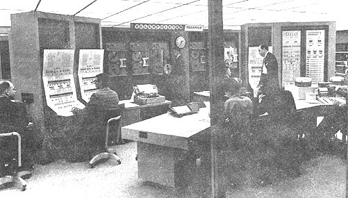 Photo by Teleregister Corporation
APPLICATIONS
General purpose computing, on-line and real-time uses
such as Banking, Airline Reservations,
Communications Switching, Passenger-Record Retrieval;
these on-line systems work with nationwide communications
networks consisting of high-speed (up to 1,200 bits sec)
and low-speed (up to 200 words/min) facilities. Switching,
terminating and transceiver apparatus for these
networks are provided by the manufacturer.
PROGRAMMING AND NUMERICAL SYSTEM
Internal number system Binary coded decimal
Decimal digits/word Variable between 1 to 100
Decimal digits/numeric digit 4 + parity
Decimal digits/alphabetic character 8 + 2 parity
Decimal digits/ instruction 8
Instructions decoded Basic: 13 arithmetic
(More than 200 depending 25 transfer
upon application). 54 branch
Arithmetic system Fixed point
Instruction type One address
Number range lo to 1099
Instruction word format
+----------------+-----------+---------------+------------------+
| Digit No. | 1 2 | 3 4 | 5 8 |
+----------------+-----------+---------------+------------------+
| Arithm. or Trf | Order No. | Length of Fld | Starting Address |
| Branch | 98 or 99 | Branch Point | Instr. Address |
+----------------+-----------+---------------+------------------+
Automatic built-in subroutines
Include automatic rerun in the event of certain failures
and programmable separation of dual system.
Automatic coding
Asset-assembler for Telefile, 1:1 Assembler
Registers and B-Boxes
Registers include Accumulator Control (ACR), Memory Control (MCR),
Instruction Control (ICR), and Quotient Control (QCR) Registers.
All orders are performed by defining field lengths in the core memory.
The addressable classification
Photo by Teleregister Corporation
APPLICATIONS
General purpose computing, on-line and real-time uses
such as Banking, Airline Reservations,
Communications Switching, Passenger-Record Retrieval;
these on-line systems work with nationwide communications
networks consisting of high-speed (up to 1,200 bits sec)
and low-speed (up to 200 words/min) facilities. Switching,
terminating and transceiver apparatus for these
networks are provided by the manufacturer.
PROGRAMMING AND NUMERICAL SYSTEM
Internal number system Binary coded decimal
Decimal digits/word Variable between 1 to 100
Decimal digits/numeric digit 4 + parity
Decimal digits/alphabetic character 8 + 2 parity
Decimal digits/ instruction 8
Instructions decoded Basic: 13 arithmetic
(More than 200 depending 25 transfer
upon application). 54 branch
Arithmetic system Fixed point
Instruction type One address
Number range lo to 1099
Instruction word format
+----------------+-----------+---------------+------------------+
| Digit No. | 1 2 | 3 4 | 5 8 |
+----------------+-----------+---------------+------------------+
| Arithm. or Trf | Order No. | Length of Fld | Starting Address |
| Branch | 98 or 99 | Branch Point | Instr. Address |
+----------------+-----------+---------------+------------------+
Automatic built-in subroutines
Include automatic rerun in the event of certain failures
and programmable separation of dual system.
Automatic coding
Asset-assembler for Telefile, 1:1 Assembler
Registers and B-Boxes
Registers include Accumulator Control (ACR), Memory Control (MCR),
Instruction Control (ICR), and Quotient Control (QCR) Registers.
All orders are performed by defining field lengths in the core memory.
The addressable classification
| BRL 1964, TELEREGISTER TELEFILE, starting page 0253
|
    is by digits. Instructions can be performed on from one to one-
    hundred digits per operand.

    ARITHMETIC UNIT
                 Incl. Stor. Access
                 Microsec
    Add        80 + 16(No. of augend + addend digits)
    Mult       80 + 16(Sum of product digits)
          (3 x     No. of multiplier + Multiplicand digits)
    Div        80 + 16   (Sum of quotient digits)
          (No. of digits in dividend)
    Construction (Arithmetic unit only)
      Transistors       2,700 to 3,000
    Arithmetic mode         Serial by digit
                            Parallel by bit
    Timing                  Synchronous
    Operation               Sequential
    Operation of input/output is concurrent on a character-
    interrupt basis.

    STORAGE
                       No. of      No. of     Access
      Medium           Chars       Digits     Microsec
    Magnetic Core      10,000                   15.0
                    or 16,000
    Magnetic Drum                  125,000   5,000
        (High-Speed)
    Magnetic Drum                1,050,000  16,700
        (Medium-Speed)
    Magnetic Disk               30,720,000 150,000
    Magnetic Tape
    No. of units that can be connected      100 Units
     No. of chars/linear inch               7 Track/tape
     Blank tape separating each record      0.5 Inches
     Tape speed                            60 Inches/sec
     Transfer rate                     24,000 Chars/sec
     Start time                             2.0 Millisec
     Stop time                              1.5 Millisec
     Average time for experienced
    operator to change reel of tape        60 Seconds
     Physical properties of tape
      Width                                 0.5 Inches
      Length of reel                    2,400 Feet
      Composition                          Mylar

    INPUT
      Medium                        Speed
    Keysets (Remote Stations)
     May use 100 words/min Teletype lines or high speed dataphone circuits.
    Typewriter Console Keyboard     10 chars sec
    Teletypewriters                 60, 75, 100 or 200 words/min
    Punched Cards                  150 cards/min
    Punched Paper-Tape              20 or 100 chars/sec
    Dial I/0 Device for           Up to 2,000 queries/min
     Stock Quotations

                 OUTPUT
      Medium                               Speed
    Keyset Printer (Remote Stations)        10 chars/sec
    Typewriter Console Keyboard             10 chars/sec
    Teletypewriter                          60, 75, 100 or 200 words/min
    Punched Cards                          150 cards/min
    Punched Paper-Tape                     100 words/min
    Line Printers                          100 words/min

    CIRCUIT ELEMENTS OF ENTIRE SYSTEM
        Type            Quantities
    Tubes                   0
    Diodes             64,000 (logic diodes)
                       30,000 (clamp & speed-up diodes)
    Transistors        12,000 (alloy junction)
                       10,000 (SBT transistors)
    Magnetic Cores
       Three 10,000 characters or 16,000 characters,
        15 microsecond memories.
    The quantities are for triplex system; i.e., three processors
    with peripheral subsystems excluding communications
    equipment.

    CHECKING FEATURES
    Parity on core output and transfer of data to and from
    peripheral equipment.

    Invalid operations in arithmetic; e.g., overflow or adding
    alphabetical characters.

    Time-out alarms if any unit does not complete its operation in
    a specified amount of time.

    Duality check including programmatic "drop-out" operation to
    end duality on error.

    Peripheral control registers may be read back and end-points
    of operation may be program checked.

    POWER, SPACE, WEIGHT, AND SITE PREPARATION
    (Typical two-processor installation)
    Power, computer   60 Kw 75 KVA 0.8 pf
    Including peripheral and communications equipment.
    Volume, computer (processor site)       35,040 cu ft
    Area, computer (processor site)  2,920 sq ft
    Room size                        40' wide, 73' long, 12' high
       Example for a typical two-processor installation.
    Floor loading       100 lbs/sq ft (avg)
                (drums)                     2,500 lbs concen max
    Weight, computer                        2,400 lbs
    Installation               60,000 lbs
    Ambient Temperature between 65o and 80oF - Dust Control
    with a filtering efficiency of 850 to 900 based upon the
    National Bureau of Standards' Dust Spot Test Method - Total
    Heat Dissipation 220,000 BTU.
    Room Size additional areas: Power Supply - 2,376 cu ft; 189
            sq ft; 22 1.; 9 w;
    12 high. Maintenance - 5,280 cu ft; 440 sq ft; 22 1; 20 w;
        12 high.

    Area dimensions adaptable according to room shape;
    installation based upon square-feet basis; square or
    rectangular shape preferred. False ceiling used as plenum for
    air-conditioning and cables.

    PRODUCTION RECORD
    Number produced to date            14
    Number in current operation        14
    Time required for delivery         14 to 18 months

    COST, PRICE AND RENTAL RATES
    Processor, random-access storage, tape handlers, and on-line
       communications channels.
    Rental contracting and rates for basic system: $30,000 and up.

    The Teleregister Corporation has a full-scale field service
    operation in more than 100 cities in U.S., servicing all
    installatins. This service organization, in existence for more
    than 30 years, operates services, and maintains Teleregister
    systems.
| BRL 1964, TELEREGISTER TELEFILE, starting page 0254
|
                               PERSONNEL REQUIREMENTS
                   (Two-processor installation, 24 hour operation)
                   One 8-Hour      Two 8-Hour     Three 8-Hour
                   Shift           Shifts         Shifts
    Supervisors      1
    Analysts    )
    Programmers )    6
    Coders      )
    Clerks           2
    Operators        2               4                6
    Engineers        1
    Technicians      2               4                6
    In-Output Oper   1               1                1

    Personnel requirements vary with the complexity of a given
    installation.

    The Teleregister Corporation trains customer personnel at its
    Stamford facility and provides onsite training as well as special
    courses on customer premises as long as required.

    RELIABILITY, OPERATING EXPERIENCE
    Teleregister on-line systems have been operating with a record of
    99.8% up-time since 1952. The systems employ duality and built-in
    controls to maintain reliability, coupled with rigid preventive
    maintenance. They have on-line capability for 24hours per day, 7-
    day per week service.

    ADDITIONAL FEATURES AND REMARKS
    High degree of flexibility of multi-processor installations for on-
    line, real-time applications with access capabilities of multi-
    processors to common storage and common input/output communications
    circuits. Expansion capability of multi-processor systems by
    addition of modules such as processors, storage, input/output and
    communications equipment due to growth of customer operations.

    FUTURE PLANS
    Additional peripheral devices, higher-speed memory
    and random-access files.

            INSTALLATIONS
                                                 No. of
       Location                                  Processors
    United Air Lines, Inc., Denver, Colo.             3
    Trans World Air Lines, New York Idlewild          2
    Howard Savings Institution, Newark, N.J.          2
    Union Dime Savings Bank, New York, N.Y.           2
    Society for Savings, Hartford, Conn.              2
    Teleregister TeleCenter, 75 Varick Street,
     New York, N.Y.                                   3
| BRL 1964, TRW 230 130 AN/UYK 1, starting page 0256
|
TRW 230 130 AN/UYK 1
Thompson Ramo Wooldridge 230 130 (AN/UYK-1)
MANUFACTURER
Thompson Ramo Wooldridge Inc.
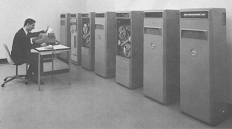 Photo by Ramo Wooldridge
APPLICATIONS
Application areas are on-line real-time processing systems such as radar
tracking, acquisition, telemetry data processing, command and control systems,
etc. High reliability and operability in adverse enviroment equips the computer
for remote cite location. A logically identical version of the TRW-130, the TRW-
230, is available for off-line scientific/ engineering applications. This is a
non-militarized computer without naval tactical data system (NTDS) communciation
channels but retaining a full line of peripheral equipment including card
input/output, magnetic tape, 300 line-per-minute printer, dataphone adapter,
magnetic drums, as well as paper tape and typewriter.
PROGRAMMING AND NUMERICAL SYSTEM
Internal number system Binary
Binary digits/word 15
Binary digits/instruction 15
Instructions/word 0, 1, 2
Instructions decoded 0, 1, 2
Arithmetic system Fixed point
Programmed floating point.
Instruction type 1, 2, or 3 address
+-------+------+------+------+
| 15 10 | 9 7 | 6 5 | 4 1 |
+-------+------+------+------+
| PC | AO | CF | SC |
+-------+------+------+------+
PC = Primary Command
AO = Address Option
CF = Control Field
SC = Secondary
Command Automatic Built-in subroutines
Wired-in boot-strap loader is initiated by the operator.
Automatic coding.
Logram level of programing allows TRW-130 to take on characteristics of the
particular application. Lograms are available for table look-up, binary-to-BCD,
gray-to-binary, curve-fit, etc., plus normal programming statements such as load,
add, store, etc.
Registers and B-Boxes
M = Instruction Counter - Memory access address
E = Decode Commands
L = Access Scratch Pad Portion of Memory
A = Arithmetic Register - Address option
P = Extention of Arithmetic Register - Address option
T = Input/Output Buffer Register
Address option is direct or indirect and may be
from the A, M, P or L Register. In the TRW-130,
indexing is accomplished without the use of a separate
hardware register and a half-adder required by most
computers. The programmer may structure the index
function with the appropriate selection of the
address option in the Logical Commands (Logands).
Thus, any core memory location may be functionally
treated as an index register. Because of a unique
"wired-in" feature, the incrementing of the particular cell chosen is done
automatically.
Photo by Ramo Wooldridge
APPLICATIONS
Application areas are on-line real-time processing systems such as radar
tracking, acquisition, telemetry data processing, command and control systems,
etc. High reliability and operability in adverse enviroment equips the computer
for remote cite location. A logically identical version of the TRW-130, the TRW-
230, is available for off-line scientific/ engineering applications. This is a
non-militarized computer without naval tactical data system (NTDS) communciation
channels but retaining a full line of peripheral equipment including card
input/output, magnetic tape, 300 line-per-minute printer, dataphone adapter,
magnetic drums, as well as paper tape and typewriter.
PROGRAMMING AND NUMERICAL SYSTEM
Internal number system Binary
Binary digits/word 15
Binary digits/instruction 15
Instructions/word 0, 1, 2
Instructions decoded 0, 1, 2
Arithmetic system Fixed point
Programmed floating point.
Instruction type 1, 2, or 3 address
+-------+------+------+------+
| 15 10 | 9 7 | 6 5 | 4 1 |
+-------+------+------+------+
| PC | AO | CF | SC |
+-------+------+------+------+
PC = Primary Command
AO = Address Option
CF = Control Field
SC = Secondary
Command Automatic Built-in subroutines
Wired-in boot-strap loader is initiated by the operator.
Automatic coding.
Logram level of programing allows TRW-130 to take on characteristics of the
particular application. Lograms are available for table look-up, binary-to-BCD,
gray-to-binary, curve-fit, etc., plus normal programming statements such as load,
add, store, etc.
Registers and B-Boxes
M = Instruction Counter - Memory access address
E = Decode Commands
L = Access Scratch Pad Portion of Memory
A = Arithmetic Register - Address option
P = Extention of Arithmetic Register - Address option
T = Input/Output Buffer Register
Address option is direct or indirect and may be
from the A, M, P or L Register. In the TRW-130,
indexing is accomplished without the use of a separate
hardware register and a half-adder required by most
computers. The programmer may structure the index
function with the appropriate selection of the
address option in the Logical Commands (Logands).
Thus, any core memory location may be functionally
treated as an index register. Because of a unique
"wired-in" feature, the incrementing of the particular cell chosen is done
automatically.
| BRL 1964, TRW 230 130 AN/UYK 1, starting page 0257
|
 Photo by Ramo Wooldridge
ARITHMETIC UNIT
Incl. Stor. Access Excl. Stor. Acces
Microsec Microsec
Add 12 6
Mutt 12 + 3n 6 + 3n
Div 12 + 3n 6 + 3n
n = number of bits
Construction (Arithmetic unit only)
Vacum-Tubes 0
Transistors 1,700
Condenser-Diodes 6,100
Magnetic-Cores 8,192
Arithmetic mode Parallel
Accuracy significance is under program control for multiplication
and divide operations. Stored logic allows ease of extending all
operations to multiple precision arithmetic.
Timing Synchronous
Operation Sequential
STORAGE
No. of No. of Bin Access
Medium Words Digits/Word Microsec
Core 8,192 to 32,768 15 3
Drum 65,536 15 15,000/block
Magnetic Tape
No. of units that can be connected 16 Units
No. of chars/linear inch 556 Chars/inch
Channels or tracks on the tape 7 Track/tape
Blank tape separating each record 0.75 Inches
Tape speed 75 Inches/sec
Transfer rate 41,700 Chars/sec
Start time 7 Millisec
Stop time 2.5 Millisec
Average time for experienced
operator to change reel of tape 120 Seconds
Physical properties of tape
Width 0.75 Inches
Length of reel 2,400 Feet
Composition Outside coated mylar
Magnetic tape is fully compatible with IBM 729 magnetic tape
systems. Tape units are housed in militarized packages.
INPUT
Medium Speed
Paper Tape 300 Chars/sec
Cards 200 Cards/min
Flexowriter 10 Chars/sec
Send/Receive Set 10 Chars/sec
OUTPUT
Medium Speed
Cards 100 Cards/min
Paper Tape 60 Chars/sec
Plotter 1/100 Inches/increment
Typewriter 10 Chars/sec
Printer 300 Line/min
Optional additional peripheral devices are a buffer channel, (input
or output 15 bit words main frame time per transmission is 9
microseconds) and a data phone or Tel-Pak Adapter. The input/output
system is oriented to on-line real-time processing by 3 parallel bi-
directional channels, two 30-bits wide and one 15-bits wide, and by
a real-time hardware interrupt system of 2-level interrupts and 11
interrupt lines.
CIRCUIT ELEMENTS OF ENTIRE SYSTEM
Type Quantity
Tubes 0
Diodes 6,100
Transistors 1,700
Magnetic Cores 8,192
CHECKING FEATURES
There is a built-in protection device to prevent loss of memory
contents in the event of a power failure. A programmed subroutine
is used to store last location of reference in case of power
failure, so as to permit resumption of computation
upon restoration of power.
    Photo by Ramo Wooldridge

    ARITHMETIC UNIT

    Incl. Stor. Access Excl. Stor. Acces

             Microsec     Microsec
    Add      12           6
    Mutt     12 + 3n      6 + 3n
    Div      12 + 3n      6 + 3n
    n = number of bits

    Construction (Arithmetic unit only)
     Vacum-Tubes           0
     Transistors       1,700
     Condenser-Diodes  6,100
    Magnetic-Cores     8,192

    Arithmetic mode     Parallel

    Accuracy significance is under program control for multiplication
    and divide operations. Stored logic allows ease of extending all
    operations to multiple precision arithmetic.

    Timing              Synchronous
    Operation           Sequential

    STORAGE
    No. of          No. of        Bin             Access
    Medium          Words         Digits/Word     Microsec
    Core        8,192 to 32,768     15              3
    Drum       65,536               15         15,000/block
    Magnetic Tape
     No. of units that can be connected            16 Units
     No. of chars/linear inch                     556 Chars/inch
     Channels or tracks on the tape                 7 Track/tape
     Blank tape separating each record              0.75 Inches
     Tape speed                                    75 Inches/sec
     Transfer rate                             41,700 Chars/sec
     Start time                                     7 Millisec
     Stop time                                      2.5 Millisec
     Average time for experienced
    operator to change reel of tape               120 Seconds
     Physical properties of tape
      Width                                         0.75 Inches
      Length of reel                            2,400 Feet
    Composition                               Outside coated mylar

    Magnetic tape is fully compatible with IBM 729 magnetic tape
    systems. Tape units are housed in militarized packages.

    INPUT
    Medium                         Speed
    Paper Tape                 300 Chars/sec
    Cards                      200 Cards/min
    Flexowriter                 10 Chars/sec
    Send/Receive Set            10 Chars/sec

    OUTPUT
    Medium                         Speed
    Cards                  100 Cards/min
    Paper Tape              60 Chars/sec
    Plotter                1/100 Inches/increment
    Typewriter              10 Chars/sec
    Printer                 300 Line/min

    Optional additional peripheral devices are a buffer channel, (input
    or output 15 bit words main frame time per transmission is 9
    microseconds) and a data phone or Tel-Pak Adapter. The input/output
    system is oriented to on-line real-time processing by 3 parallel bi-
    directional channels, two 30-bits wide and one 15-bits wide, and by
    a real-time hardware interrupt system of 2-level interrupts and 11
    interrupt lines.

    CIRCUIT ELEMENTS OF ENTIRE SYSTEM
       Type             Quantity
    Tubes                     0
    Diodes                6,100
    Transistors           1,700
    Magnetic Cores        8,192

    CHECKING FEATURES
    There is a built-in protection device to prevent loss of memory
    contents in the event of a power failure. A programmed subroutine
    is used to store last location of reference in case of power
    failure, so as to permit resumption of computation
    upon restoration of power.
| BRL 1964, TRW 230 130 AN/UYK 1, starting page 0258
|
    POWER, SPACE, WEIGHT, AND SITE PREPARATION
    Power, computer      0.6 Kw  0.6 Kva
    Volume, computer    10.9 cu ft
    Area, computer       4.4 sq ft
    Floor loading        25  lbs/sq ft
                         25  lbs concen max
    Weight, computer    550  lbs
    An air conditioner is not required.

    PRODUCTION RECORD
    Number produced to date             70
    Number in current operation         70
    Number in current production       125
    Number on order                    122
    Anticipated production rates         4/week
    Time required for delivery           3 months

    COST, PRICE AND RENTAL RATES
    TRW    Basic System/Component         Purchase     Monthly
    Model                                 Price        Lease

    130    Digital Computer               $ 73,430     $ 2,050
    140    Input/Output Controller          14,750         375
    151    Paper Tape Reader/Reefer          5,025         130
    161    Paper Tape Punch                  1,625          40
    185    Input/Output Typewriter           3,300          85
    141    I/0 Controller Grp (incl.
           Read/Reeler,Punch, & Type-
            writer)                         30,500         780
    170    Magnetic Tape Unit               23,000         610
    192    Magnetic Tape Controller         22,000         580

    1921   Magnetic Tape Controller Kit      2,600          90
    1721   Extended Core Memory Unit w/
             8,192 Word Memory              42,000       1,200
    1722   Extended Core Memory Unit w/
            16,384 Word Memory
    1723   Extended Core Memory Unit w/
            24,576 Word Memory
    171    Magnetic Drum Memory w/65,000
             Word Memory
    1731   Buffer Channel (mounted in
             TRW-1721)                      22,950         640
    187    Flexowriter                      14,000         445
    188    Serial Send/Receive Set w/
             Teletype Unit                   3,250          80

    186    Send/Receive Set                 3,900          120
    193    Static Voltage Regulator           515           20
    194    Motor Alternator Set             4,250          130
    256    Card Reader, 200 cds/min        17,500          470
    257    Card Punch                      17,250          470
    266    X-Y Plotter                      9,500          295
    282    Med. Speed Line Printer,
              300 lines per minute         30,000          900
    On site maintenance rates vary greatly with location.
    Rates are available upon request.

    PERSONNEL REQUIREMENTS
                 One 8-Hour Two 8-Hour   Three 8-Hour
                 Shift      Shifts       Shifts
    Programmers    1          2           3
    coders         1          2           3
    Operators      1          2           3

    Training made available by the manufacturer to the user includes
    maintenance and operator training and programming instruction. Other
    services available are manuals, field engineering, programming
    consultation and services, applications and system engineering.
    Operational maintenance is possible by "on call basis"
    due to high reliability. Design for remote site location reduces number
    of operational personnel.

    Programming Training Course (1 week) at Canoga Park subject to RW
    schedule for minimum group of six. No charge.

    Maintenance Training Course (7 weeks) at Canoga Park subject to RW
    schedule for minimum group of six. 7,380/class or 250/student-week.

    RELIABILITY, OPERATING EXPERIENCE

    The computer has been operating in the field in many varied
    installations. The originally projected 896 hours mean time operation
    between failures has been exceeded. In one remote site installation the
    computer has been operating for over 7,500 hours without a single
    component failure. Field experience to date indicates an MTBF in excess
    of 1,000 hours for the mid-1962 system installations. The entire system
    design, i.e., stored logic, and all construction techniques were
    predicated on the objective of obtaining extreme reliability and
    simplified operation and maintenance under extreme environmental
    conditions. Due to reduced component count and premium component
    selection, additional self-checking features are not considered as
    reliability improvements. Over 140,000 hours operating time have been
    accumulated as of 30 April 1963.

    ADDITIONAL FEATURES AND REMARKS

    Outstanding features include military specification design and
    production, proven operating record in shipboard installation, mufti-
    level automatic interrupt, and stored logic. Unique system advantages
    include mufti-computer and peripheral hook-up feasibility and provisions
    for maximum number of peripheral devices, without field retrofit.

    No special procedures are required for the handling of magnetic tape.

    The TRW-130 (AN/UYK-1) is designed for ruggedness. (It can operate in
    adverse environments--on board ship or land).

    Small size. (The entire computer, without dismantling, can be loaded
    into and maneuvered within confined quarters).

    Compatibility with NTDS    (It can communicate with
    Navy Tactical Data System (NTDS) peripheral equipmentl
    and inexpensiveness     (It is economically justified
    even for small tasks).

    Stored Logic Design. The TRW-130's stored logic design effects both
    hardware and software--hardware in that many circuit components are
    eliminated, thereby reducing size, weight and construction and
    increasing reliability. Software in that a logical organization best
    suited for the application may be specified. At the micro-command level
    of coding, extreme efficiency and flexibility may be obtained.

    FUTURE PLANS

    Design is nearing completion for the second generation TRW-130 computer
    to be called the TRW-133. The most significant difference between this
    computer and the TRW-130 (AN/UYK-1) is that all internal operation times
    have been reduced by a factor of three, yet complete program
    compatibility with the TRW-130 has been maintained.
| BRL 1964, TRW 230 130 AN/UYK 1, starting page 0259
|
 Diagram by Ramo Wooldridge
Logical Organization
The TRW-230's logical organization is shown above.
The six 15-bit registers have deliberately been given
noncommittal names becuase few of them have distinctive
functions. (Most instructions do not include memory
addresses, but rather addressing options that reference
the present contents of the M, A, or P register as
an address.
The M register controls all memory accesses except
those made through the L register to scratchpad addresses
0-63. Before A or P are used as an address, their contents
are exchanged with M, and after use M is always
restored. In this way M is used to access operands, and
also serves as the instruction counter. For the
latter purpose M is always incremented at least once
during each instruction.
The E register is the memory exchange register,
and is also an input-output register, It holds operands
during iterative instructions and does a few other odd
jobs from time to time.
The L register holds instructions during execution,
holds operands temporarily between instructions on
occasion, and may be used to address the 64 words of
scratchpad memory.
The A register is the principal arithmetic register
and resembles a conventional accumulator under most
circumstances. The contents of A may be used as an
address, also.
The P register is a secondary arithmetic register
and usually resembles a multiplier-quotient register.
Its contents may also be used as an address, and
frequently P is employed to control a program sequence in
the interpretive mode.
The T register is chiefly used as an input-output
buffer for slow-speed devices, but when not needed for
this purpose, it can be used to store intermediate
operands from A or E.
The other registers are a parallel full-adder,
a parallel half-adder, an overflow indicator and a carry
flip-flop. All transfers from the M register pass
through the address counter, where the previous contents
of M may be incremented by unity. The programmer
controls this function except when the instruction address
is incremented.
     Diagram by Ramo Wooldridge

                                Logical Organization

     The TRW-230's logical organization is shown above.
    The six 15-bit registers have deliberately been given
    noncommittal names becuase few of them have distinctive
    functions. (Most instructions do not include memory
    addresses, but rather addressing options that reference
    the present contents of the M, A, or P register as
    an address.

     The M register controls all memory accesses except
    those made through the L register to scratchpad addresses
    0-63. Before A or P are used as an address, their contents
    are exchanged with M, and after use M is always
    restored. In this way M is used to access operands, and
    also serves as the instruction counter. For the
    latter purpose M is always incremented at least once
    during each instruction.

     The E register is the memory exchange register,
    and is also an input-output register, It holds operands
    during iterative instructions and does a few other odd
    jobs from time to time.

     The L register holds instructions during execution,
    holds operands temporarily between instructions on
    occasion, and may be used to address the 64 words of
    scratchpad memory.

     The A register is the principal arithmetic register
    and resembles a conventional accumulator under most
    circumstances. The contents of A may be used as an
    address, also.

     The P register is a secondary arithmetic register
    and usually resembles a multiplier-quotient register.
    Its contents may also be used as an address, and
    frequently P is employed to control a program sequence in
    the interpretive mode.

     The T register is chiefly used as an input-output
     buffer for slow-speed devices, but when not needed for
    this purpose, it can be used to store intermediate
    operands from A or E.

     The other registers are a parallel full-adder,
    a parallel half-adder, an overflow indicator and a carry
    flip-flop. All transfers from the M register pass
    through the address counter, where the previous contents
    of M may be incremented by unity. The programmer
    controls this function except when the instruction address
    is incremented.
| BRL 1964, TRW 330, starting page 0260
|
TRW 330
Thompson Ramo Wooldridge 330
MANUFACTURER
Thompson Ramo Wooldridge, Inc., TRW Computers Co.
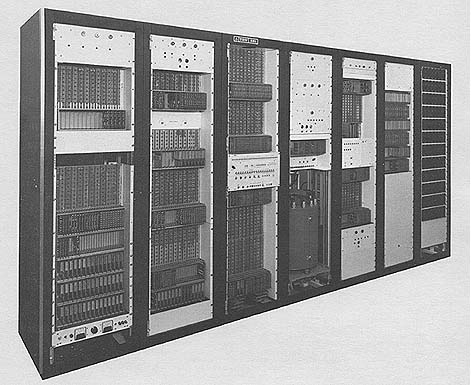 Photo by Thompson Ramo Wooldridge, Inc.
APPLICATIONS
On-line, real time, process, power, test and control system.
At the Riverside Cement Company plant at Oro Grande, California, a
TRW computer is controlling two 310-foot dry-process kilns. The
computer also makes daily calculations for quarrying and blending
raw materials, keeps a complete record of the origin, weight, and
chemical composition of these materials, and logs kiln data.
A major overseas glass producer has installed two TRW computers in
a system to automate a glass cutting plant. The computer system has
made it possible to integrate factory operations, from the receipt
of the order from the customer to the delivery of the completed job
to the customer.
At its nuclear power plant near Chinon, France, Electricite de
France is using two TRW computers on
the EDF-1 reactor. These two computer systems continuously monitor
the radioactivity of carbon dioxide cooling gas as it flows through
1149 channels in the nuclear reactor. On a rise in radioactivity-
which denotes a rupture of the uranium fuel casesthe computers are
programmed to initiate immediate corrective action.
Two TRW computers are being used by Electricite de France to
control a 250-megawatt steam power generating station at St. Ouen,
France. The computer system monitors more than 600 process
variables and automatically controls plant operation to minimize
power out-put costs.
In 1963, Electricite de France will start using a TRW computer for
control of power dispatching. The computer will be located in
Paris, at the center of the EDF grid that carries power throughout
France.
Photo by Thompson Ramo Wooldridge, Inc.
APPLICATIONS
On-line, real time, process, power, test and control system.
At the Riverside Cement Company plant at Oro Grande, California, a
TRW computer is controlling two 310-foot dry-process kilns. The
computer also makes daily calculations for quarrying and blending
raw materials, keeps a complete record of the origin, weight, and
chemical composition of these materials, and logs kiln data.
A major overseas glass producer has installed two TRW computers in
a system to automate a glass cutting plant. The computer system has
made it possible to integrate factory operations, from the receipt
of the order from the customer to the delivery of the completed job
to the customer.
At its nuclear power plant near Chinon, France, Electricite de
France is using two TRW computers on
the EDF-1 reactor. These two computer systems continuously monitor
the radioactivity of carbon dioxide cooling gas as it flows through
1149 channels in the nuclear reactor. On a rise in radioactivity-
which denotes a rupture of the uranium fuel casesthe computers are
programmed to initiate immediate corrective action.
Two TRW computers are being used by Electricite de France to
control a 250-megawatt steam power generating station at St. Ouen,
France. The computer system monitors more than 600 process
variables and automatically controls plant operation to minimize
power out-put costs.
In 1963, Electricite de France will start using a TRW computer for
control of power dispatching. The computer will be located in
Paris, at the center of the EDF grid that carries power throughout
France.
| BRL 1964, TRW 330, starting page 0261
|
    PROGRAMMING AND NUMERICAL SYSTEM

    Internal number system         Binary
    Binary digits/word             28 (Including sign)
    Binary digits/instruction      28
    Instructions/word               1
    Instructions decoded           93 (Basic)
     284 with all instruction options.
    Arithmetic system  Fixed point
    Twos complement notation for negative numbers.
    Instruction type   One address
    Number range Octal -777777777 to +777777777
                 = D to ± 134,217,727 Decimal
    Instruction word format
    +---------+-------+----------+-------+-------+-------+-------+--------+
    | 28      |  27   | 26    25 | 24 20 | 19    |   18  | 17  8 | 7    1 |
    +---------+-------+----------+-------+-------+-------+-------+--------+
    | Delayed | Oper- | Instruc  | Basic | Index | Spare | Oper- | Oper-  |
    | Tag     | and   | Modifier | Op    | Tage  |       | and   | and    |
    |         | Mode  |          | Code  |       |       | Track | Sector |
    +---------+-------+----------+-------+-------+-------+-------+--------+
    |    Operation Code                          |   Operand Field        |
    +--------------------------------------------+------------------------+
    Automatic built-in subroutines

    Wired square root command. Take 26 bit square finds
       13 bit root in 2128 microseconds.

    Automatic coding.

    The PROCOMP Software system includes: Special job-oriented statements-
    -one statement compiles from 2 to machine language instruction.
       FORTRAN
    Registers and B-Boxes
    6 program accessable registers: 3 at 28 bits; 1 at 17 bits, 1 at 16
    bits, 1 at 8 bits.
    One of the registers is the Index Register: 16 bits

     ARITHMETIC UNIT
           Incl. Stor. Access      Excl. Stor. Access
           Microsec                Microsec
    Add       266                    133
    Mult      -                       (3 + n) 133
    Div       -                       (4 + n) 133
    Above is for full words.
       Construction (Arithmetic unit only)
     Vacum-Tubes        0
     Transistors    2,065
     Diodes         9,315
    Arithmetic mode Serial
    Timing          Synchronous
    Operation       Sequential (modified)

    There are several operating modes provided to reduce effective
    average access time/instruction. The normal mode operates on a two-
    word sequential cycle for next instruction pick-up.

    A delay mode allows the programmer to use the current operand address
    as the basis for the next instruction pick-up.

    STORAGE
                   No. of     No. of          Access
    Medium         Words      Digits        Microsec
    Drum          8,000 -     224,000 to       8,500 (Avg)
                130,000     3,640,000

    INPUT
    Medium                       Speed
    Paper Tape (Flexowriter)     10 chars/sec
    Paper Tape (High Speed)      60 chars/sec
    Cards (IBM 026)              12 cards/min
    Digital Input Console
    Analog Signals

    OUTPUT
       Medium                       Speed
    Paper Tape                  10-60 chars/sec
    Typewriter                  10 chars/sec
    Cards                       12 cards/min
    Digital Output Signals
    Analog Signals

    CIRCUIT ELEMENTS OF ENTIRE SYSTEM
    Type                         Quantity
    Tubes                               0
    Diodes                         12,421
    Transistors                     2,745
    Magnetic Cores                      0

     CHECKING FEATURES
    A parity check is performed on all information transfers from memory.
    There are marginal checking features.

    Programmed self-check and a hardware timer that the computer program
    must reset regularly are optional.

   POWER, SPACE, WEIGHT, AND SITE PREPARATION
    Volume, computer              4 cu ft
    Area, computer               12 sq ft
    Floor loading           150 lbs/sq ft
                            500 lbs/sq ft concen mar
    Site preparation requirements

    A 120-volt, 60 cycles/sec line and conduits for cables are all the
    installation requirements necessary. An air conditioner is not
    required.

    PRODUCTION RECORD
    Number in current operation         8
    Number on order                    22

    COST, PRICE AND RENTAL RATES
    Maintenance/service contracting cost about $1,000 month for a typical
    system. The cost varies with complexity of system and the location
    (geographic) of the installation.

    PERSONNEL REQUIREMENTS
               One 8-Hour   Two 8-Hour   Three 8-Hour
                Shift       Shifts       Shifts
    Operators      1          2             3
    Engineers      0          0             1

    The training made available by the manufacturer to the user includes
    a control computer system course, a programming course, and a theory
    of operation and maintenance course. Generally, customers will have a
    manufacturer-designated programmer. His participation is greatest
    before installation. Usually phasing out once system goes on-line.

    RELIABILITY, OPERATING EXPERIENCE
    Better than 99.3% reliability with 24-hour/day online operation.
| BRL 1964, TRW 330, starting page 0262
|
                          ADDITIONAL FEATURES AND REMARKS

    Outstanding features include flexible and I/0 Units, special analog scan command, hi-
    low limit checks, 128 inputs in 34 milli seconds, the storage and I/0 units are
    field expandable.

    Union Carbide Olefins Company is using a TRW computer for closed-loop control of a
    chemical plant at Seadrift, Texas. The plant produces petrochemicals.

    Traffic on Los Angelest Sunset Boulevard is being controlled by a TRW computer
    system. The computer analyzes and directs traffic patterns to maintain maximum flow,
    reacting instantaneously to changing traffic conditions on the crowded thoroughfare.

    TRW Computers has delivered an advanced mobile computer center to Phillips Petroleum
    Company in Bartlesville, Oklahoma. The mobile system--called "Computermobile"--is a
    complete process control center, and is housed in a custom-built, 40-foot trailer.
    Heart of the Computermobile is a TRW digital control computer. A major advantage of
    this unit is that it can be moved readily and connected rapidly to equipment in
    Phillips plants to perform special measurements, data logging, analysis, and process
    control functions.

    A computer system which will keep a constant check on plant conditions and
    operations has been applied to Continental Oil Company's new $10,000,000 "ALFOL"
    industrial alcohol plant at Lake Charles, Louisiana. The products are used
    principally in the synthetic detergent and plastics industries. The TRW control
    computer system is used primarily to compute various unit operations factors, to
    monitor and log data during and after startup of the plant, to follow trends through
    digital printouts of both measured and calculated variables, and to monitor and
    check instruments and equipment.

    A major steel producer has ordered a TRW computer system, for delivery in the fall
    of 1963, that will be used to conduct dynamic process studies of the basic oxygen
    furnace process.

    Early in 1964, an international oil company will install at TRW control computer on
    a catalytic cracking unit. With this computer system, the company will undertake a
    major research project to study and evaluate the merits on on-line computer control
    of the cracking unit. The project will also investigate the feasibility of using the
    computer to integrate refinery operations.

    INSTALLATIONS

    The following are TRW computer installations, not necessarily the TRW 330:

    Chichibu Cement Co., Kumagaya, near Tokyo, Japan
    Tokuyama Soda Co., Ltd., Tokuyama City, Japan
    Electricite de France, Chinon, France
    Tennessee Valley Steam Plant Nr. 5, Drakesboro, Ky
    Bull Run Steam Plant, Edgemoor, Tennessee (1964)
    Federal Aviation Agency's Experimental Center,
     Atlantic City, New Jersey
    B.F. Goodrich Goal. Plant, Calvert City, Ky
    Monsanto Chemical Co., Luling, Louisiana
    Celanese Corp. of America, Bishop, Texas
    Badische Anilin & Soda-Fabrik AG, West Germany
    Firestone Tire & Rubber Co., Lake Charles, La.
    Petroleum Chemicals Inc., Lake Charles, La.
    Allied Chemical Corp., Ironton, Ohio
    Nippon Petrochemicals Co. Ltd., Kawasaki, Japan
    Phillips Petroleum Co., Borger, Texas
    Monsanto Chemical Co., El Dorado, Arkansas

                                           OPERATING TIME,
    GENERALIZED COMMAND LIST               MILLISECONDS
     Load, Store, and Register Transfer      0.26
     Add, Subtract, and Index                0.26
     Multiply
       7-bit multiplier                      1.30
      14-bit multiplier                      2.21
      21-bit multiplier                      3.12
      27-bit multiplier                      3.90
     Divide
       7-bit quotient                        1.43
      14-bit quotient                        2.34
      21-bit quotient                        3.25
      27-bit quotient                        4.03
     Square Root                             2.08
     Jump                                    0.26
     Extract and Merge                       0.26
     Shift                           0.13 +  0.13/place
     Block Transfer                          0.26/word
     Analog (Hi-Lo Limit) Scan               0.26/word
     Digital Input                           0.26
     Digital Output                          0.26
    * Start Digital Output Buffer            0.26

    * Buffer automatically outputs up to 712 numeric or 572 alphanumeric characters.
    After ordering the output, the computer is free to continue with its program. A
    signal is received when the block output has been completed.
| BRL 1964, TRW 330, starting page 0263
|
TRW-330 INPUT/OUTPUT SUBSYSTEMS
|
INPUT/OUTPUT
| Operator's console, with indicators, displays, pushbuttons,
and multi-position switches.
|
|
EQUIPMENT
| typewriters. Paper-tape readers and punches. Magnetic tape units. Punched card
input/output.
The analog input subsystem accepts variable-voltage inputs from
instruments that measure
|
|
ANALOG INPUTS
| pressures, flows, temperatures, and other process conditions. The basic
subsystem can provide fm up to 1024 analog inputs; more can be accommodated
by adding extra modules.
Through a buffer, the inputs are automatically sequenced into
memory at the nominal rate
of 60 per second; no program running time is consumed for this
operation; however, the
frequency and sequence in which instrument values are read
can be changed by program
control. Higher input rates are available in special system configurations.
|
|
ANALOG OUTPUTS
| The analog output subsystem uses data words in memory to regulate
controller setpoints
and adjust valves and other controls. The basic subsystem can
provide for up to 128 analog
outputs; more can be a commodated by adding extra modules.
Through a buffer, these data
words are converted to analog values and automatically
applied to output devices; again,
no program running time is consumed for this operation.
The settings of the output devices
are maintained by individual memory elements. Output
signals can be pulses of fixed or vari-
able duration, or currents or volcages in a variety
of ranges. Program-controlled outputs
can also be supplied.
|
|
DIGITAL INPUTS
| The digital input subsystem accepts input signals that represent the
on-or-off status of
switch or relay contacts, time-of-day signals, and information from operator-controlled equip-
ment. The basic subsystem can provide for up to 829 digital inputs; more can be accom-
modated by adding extra modules. The digital input subsystem can include pulse counters
and sequence event recorders, in which digital inputs are used to accumulate counts of events
and the order in which closely spaced events occur; these systems operate without inter-
rupting the computer's control or data-gathering program; event sequences can be recorded
at rates up to 60 per second, and count signals can be recorded at rates up to several thousand
per second.
|
|
DIGITAL OUTPUTS
| The digital output subsystem provides signals for on-off control and
for operator communication via peripheral output equipment. The basic subsystem can provide for up to 576 digital
outputs; more can be accommodated by adding extra modules. Where advisory control is desir-
able, special displays can be provided at remote operating locations; these displays use alpha-
numeric symbols and indicator lights to present data in engineering units. Pulse train outputs
can be provided for stepping operations or motor jogging.
|
|
PRIORITY INTERRUPT
| The interrupt subsystem allows conditions outside the TRW-330 to
interrupt computations;
the computer retains the partial results of calculations in memory while it responds to the
interrupt; after handling the emergency, and if necessary, warning the operator, the 330
resumes its calculations at the place where it was interrupted. The priority interrupt system
can handle a number of separate interrupt sources in the order of their importance both with
respect to each other and to the program in progress; for each interrupt line, the 330 has a
unique response, so that no executive routine is required to locate the interrupt source. The
basic priority interrupt subsystem can provide for up to 92 interrupt lines; more can be
accommodated by adding extra modules.
|
|
FAIL-SAFE DESIGN
| Fail-safe and self-check features are an integral part of the design
and programming of TRW
computer systems. Equipment or power failure of any kind causes automatic lockup of all
controllers at their most recently calculated setpoints. Any output or outputs may be taken off
computer control and controlled manually. A fail-safe detector restarts the program and alerts
the operator if it is not reset by the computer program at regular intervals.
|
|
EXPERIENCE
| Every TRW-330 system includes the experience-in analysis, design, manufacturing, installa-
tion, and startup-of the world's leading control computer organization.
|
| BRL 1964, TRW 340, starting page 0264
|
TRW 340
Thompson Ramo Wooldridge 340
MANUFACTURER
Thompson Ramo Wooldridge, Inc., TRW Computers Co.
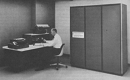 Photo by Thompson Ramo Wooldridge, Inc.
APPLICATIONS
On-line, real-time process or test control system.
PROGRAMMING AND NUMERICAL SYSTEM
Internal number system Binary
Binary digits/word 28
Binary digits/instruction 28
Instructions/word 1
Instructions decoded 109
Arithmetic system Fixed point
Instruction type One address
Number range 0 to ± 134,217,727
Instruction word format
+--------+------------------+-------+------+---------------+
| 29 | 27 26 22 21 18 | 17 16 | 15 | 14 1 |
+--------+------------------+-------+------+---------------+
| Parity | Mode Modi- Basic | Index | Rel. | |
| | fiers Oper. | Desig | Tr. | |
| | Code | | Mode | |
| | Operation Code | | | Operand Field |
+--------+------------------+-------+------+---------------+
+--------+------+------------------------------------------+
| 29 | 28 | 27 1 |
+--------+------+------------------------------------------+
| Parity | Sign | Magnitude |
+--------+------+------------------------------------------+
Automatic built-in subroutines
Bootstrap Loader
Binary to BCD and BCD to Binary Conversions
Automatic coding
There is a PROCOMP software package.
Registers and B-Boxes
There are 5 programmable registers + accumulation + optional registers,
for interrupt, etc.
ARITHMETIC UNIT
Incl. Stor. Access Excl. Stor. Access
Microsec Microsec
Add 16 8
Mult 68 62
Div 80 74
Above times are for full length words.
Arithmetic mode Parallel
Timing Synchronous
Operation Sequential
STORAGE
No. of No. of Access
Medium Words Digits/Word Microsec
Magnetic Core 4,000- 29 6
65,000
Magnetic Drum 8,000- 32 8,330
130,000
Magnetic Tape
Channels or tracks on the tape 7 Track/tape
The magnetic tape characteristics are under development.
Photo by Thompson Ramo Wooldridge, Inc.
APPLICATIONS
On-line, real-time process or test control system.
PROGRAMMING AND NUMERICAL SYSTEM
Internal number system Binary
Binary digits/word 28
Binary digits/instruction 28
Instructions/word 1
Instructions decoded 109
Arithmetic system Fixed point
Instruction type One address
Number range 0 to ± 134,217,727
Instruction word format
+--------+------------------+-------+------+---------------+
| 29 | 27 26 22 21 18 | 17 16 | 15 | 14 1 |
+--------+------------------+-------+------+---------------+
| Parity | Mode Modi- Basic | Index | Rel. | |
| | fiers Oper. | Desig | Tr. | |
| | Code | | Mode | |
| | Operation Code | | | Operand Field |
+--------+------------------+-------+------+---------------+
+--------+------+------------------------------------------+
| 29 | 28 | 27 1 |
+--------+------+------------------------------------------+
| Parity | Sign | Magnitude |
+--------+------+------------------------------------------+
Automatic built-in subroutines
Bootstrap Loader
Binary to BCD and BCD to Binary Conversions
Automatic coding
There is a PROCOMP software package.
Registers and B-Boxes
There are 5 programmable registers + accumulation + optional registers,
for interrupt, etc.
ARITHMETIC UNIT
Incl. Stor. Access Excl. Stor. Access
Microsec Microsec
Add 16 8
Mult 68 62
Div 80 74
Above times are for full length words.
Arithmetic mode Parallel
Timing Synchronous
Operation Sequential
STORAGE
No. of No. of Access
Medium Words Digits/Word Microsec
Magnetic Core 4,000- 29 6
65,000
Magnetic Drum 8,000- 32 8,330
130,000
Magnetic Tape
Channels or tracks on the tape 7 Track/tape
The magnetic tape characteristics are under development.
| BRL 1964, TRW 340, starting page 0265
|
    INPUT
    Medium              Speed
    Paper Tape          10-300,chars/sec
    Cards                 300 cards/min
    Magnetic Tape           Variable
    Analog Signals from instrumentation
    Digital Signals from operator and process
    Digital Clock

   OUTPUT
    Medium              Speed
    Paper Tape      10-100 chars/sec
    Typewriter         10 chars/sec
    Cards             100 cards/min
    Magnetic Tape          Variable

    Analog Signals to instrumentation
    Digital Signals to operator and process
      80-column cards are used.

    CIRCUIT ELEMENTS OF ENTIRE SYSTEM
    Type                Quantity
    Tubes                   0
    Diodes              5,700
    Transistors         1,830
    Capacitors            712
    Resistors           6,075
    Flip-Flops             64
    Magnetic Cores    120,000 to 480,000

    CHECKING FEATURES

    Marginal checking features are built in.

    Parity checking is done on the drum and core storage units
    and on the transfers.

    There is a programmed self-check available, and a watch-dog
    timer that the computer resets regularly.

                     POWER, SPACE, WEIGHT, AND SITE PREPARATION

    Power, computer      1 Kw
    Volume, computer    84 cu ft
    Area, computer      12 sq ft
    Floor loading     125 lbs per sq ft

    Weight, computer 1,500 lbs

    Input-output elements are not included in the above figures.
    Site preparation requirements

    120v, 60 cycles/second, single-phase power, with conduits
    for interconnecting cables are all that are required. An air
    conditioner is not required.

     PRODUCTION RECORD
    Time required for delivery  12 months

    COST, PRICE AND RENTAL RATES
    Maintenance and service contracting cost about 16,000 per
    year.

    PERSONNEL REQUIREMENTS
                 One 8-Hour Two 8-Hour Three 8-Hour
                  Shift     Shifts     Shifts
    Operators      1         2          3
    Engineers      0         0          1

    Training made available by the manufacturer to the user
    includes a control computer system course, a programming
    course, a theory of operation and maintenance course, and a
    process analysis course.

    RELIABILITY, OPERATING EXPERIENCE

    The TRW-340 design is based on operating experience with
    successful computer control installations that have logged
    over half a million hours of on-line, twenty-four-hour-per-day
    operation with reliability better than 9

    ADDITIONAL FEATURES AND REMARKS

    Outstanding features include the flexibility of memory size,
    full-expandability of memory and inputoutput, and a 990
    reliability in round-the-clock operation.

                                              OPERATING TIME,
                                                MICROSEC (INCL. MEMORY
    GENERALIZED COMMAND LIST                    ACCESS TIME)

      Load, Store, and Register Transfer         16
    Add, Subtract, and Index . . . . . . . . . . 16
    Multiply
    7 bit multiplier . . . . . . . . .  . . . . 131
       14 bit multiplier . . . . .  . .  . . . .245
       21 bit multiplier . . . . . .   . . . . .359
       27 bit multiplier . . . . . .   . . . . .457
    Divide
        7 bit quotient . . . . .        . . . . 147
       14 bit quotient . . . .     . . . . . . .261
       21 bit quotient . . . . .   . . . . . . .375
       27 bit quotient . . . . . .   . . . . . .473
    Square Root ............                    228
    Jumps...................                     16

    Extract and Merge . . . . .    . . . . . . . 16

   Shifts
      0-7 places .............                   16
      8-15 places ............                   33
      16-23 places ...........                   49
      24-31 places ...........                   66
      Core Searches ..........                   16/word
      *BIockTransfer, Core/Drum and Drum/Core . 130/word
    -Block Transfer, Drum/Drum .   . . . . . . .260/word
    -Hi-Lo Limit Drum Scan . . . . .   . . . . .260/word
      -Digital Input Drum Scan              ..   10/lin
      Digital Input .    .    ..   ...  .  .   . 16
    Digital Output . .. . . . .  . . . . . . . . 16

 .    * These commands are executed off-line; for core/drum and
      drum/core block transfers, the program is automatically
      "frozen" for 16 microseconds every 130 microseconds until transfer is
      complete; for the others, only 16 microseconds of
      actual program operating time are required.
      At the end of a block transfer, an interrupt signals
      completion; this interrupt may be masked if
      not needed. At the end of a drum scan, one of
      two interrupts signals whether scan was
      successful or not.


Go To Table of Contents