|
|
right is PH-58 from Larry Croll
Helicopter image from Bill Shaw, 80 K Bytes
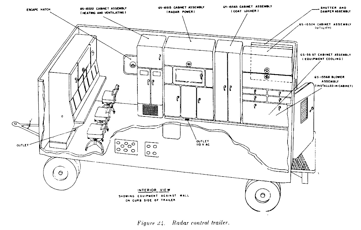
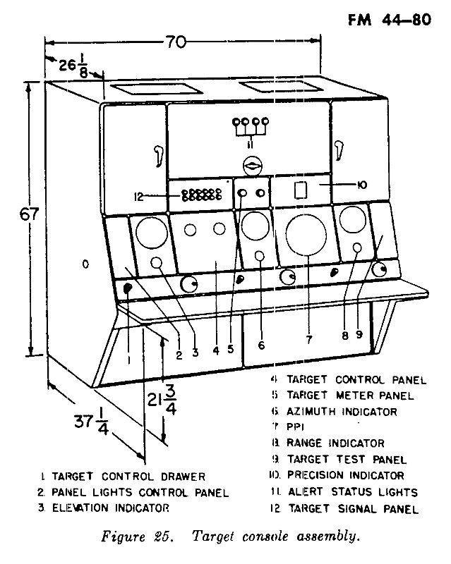
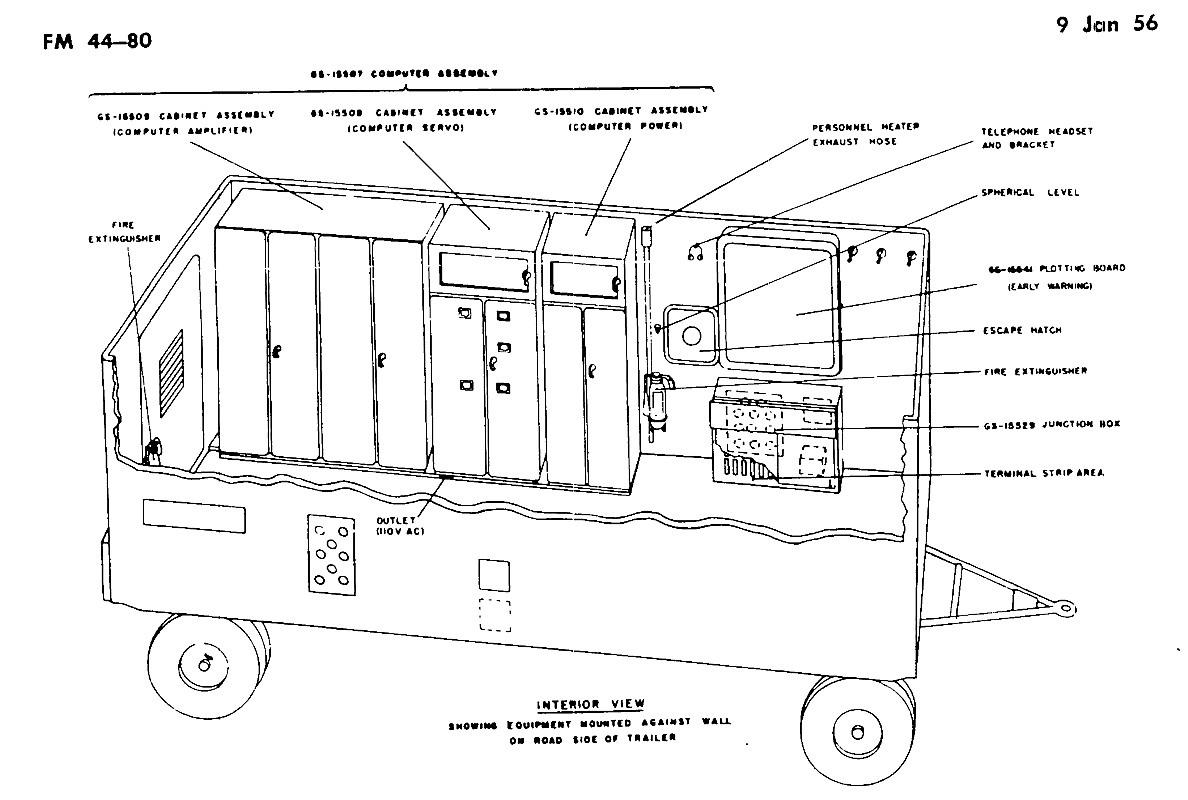
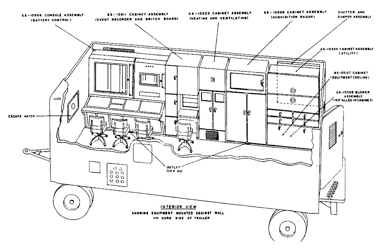
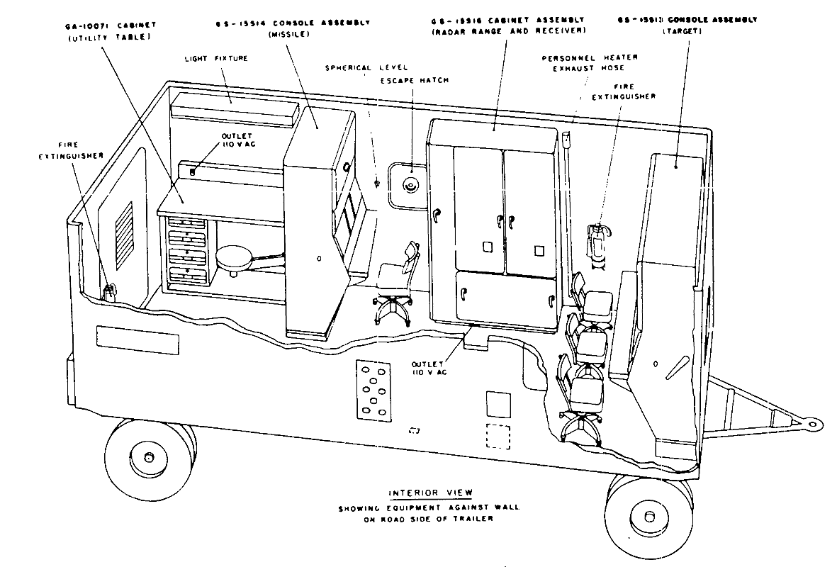
TM-9-1430-253-12-4 - Chapter 3 Overall Physical description of the Radar Course Directing Central - Improved NIKE-HERCULES from Josef Wiesner
Return to home page, Goto Next Section
|
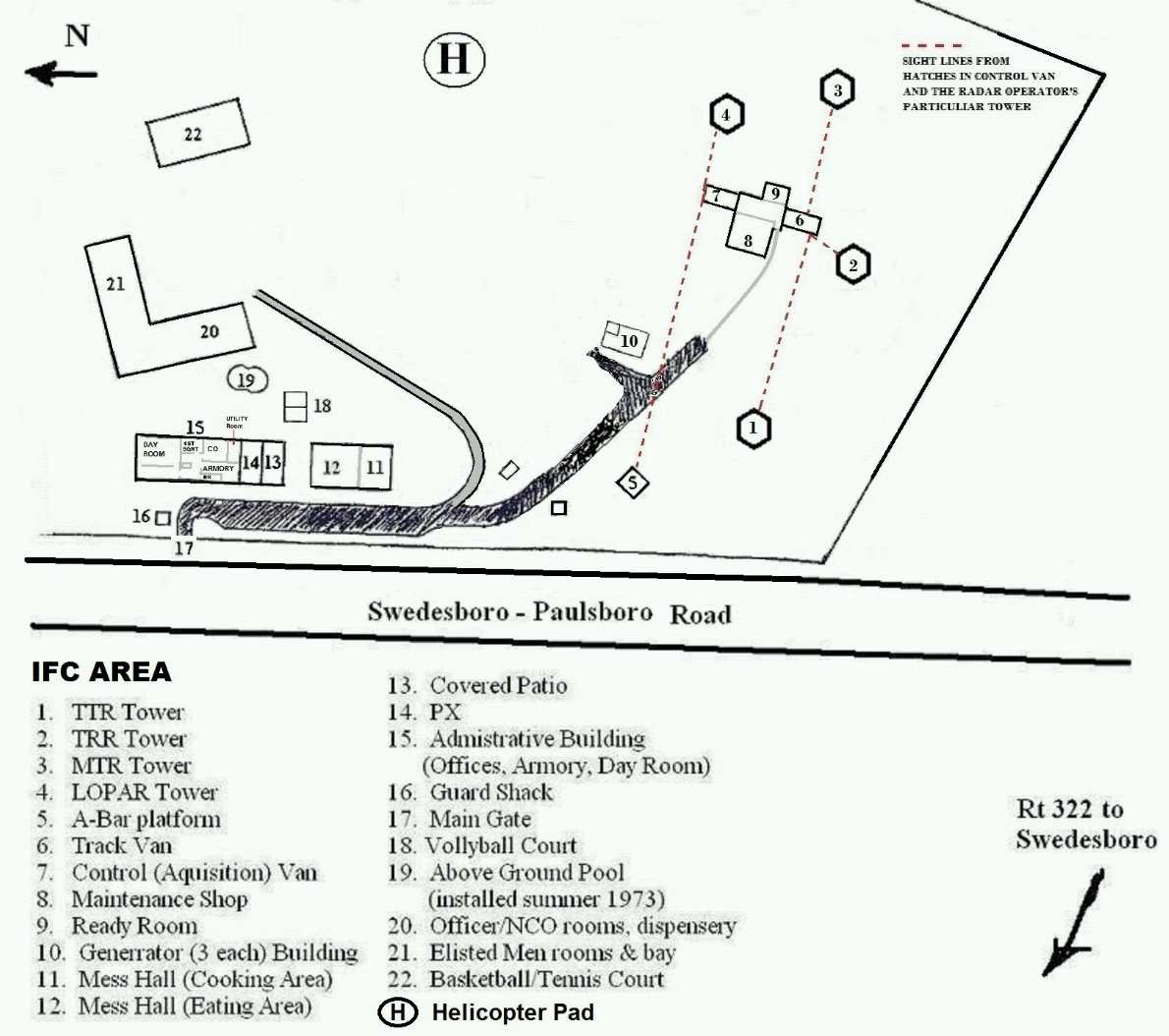
"typical" IFC Plan Views
right is PH-58 from Larry Croll |
|
Bristol IFC, Hercules, before installing
Improved Hercules (TRR and HIPAR), Helicopter image from Bill Shaw, 80 K Bytes |
|
|
Ft. Duvall IFC, Improved Hercules (TRR and HIPAR), from
Tom Page, 70 K Bytes
TM-9-1430-253-12-4 - Chapter 3 Overall Physical description of the Radar Course Directing Central - Improved NIKE-HERCULES from Josef Wiesner |
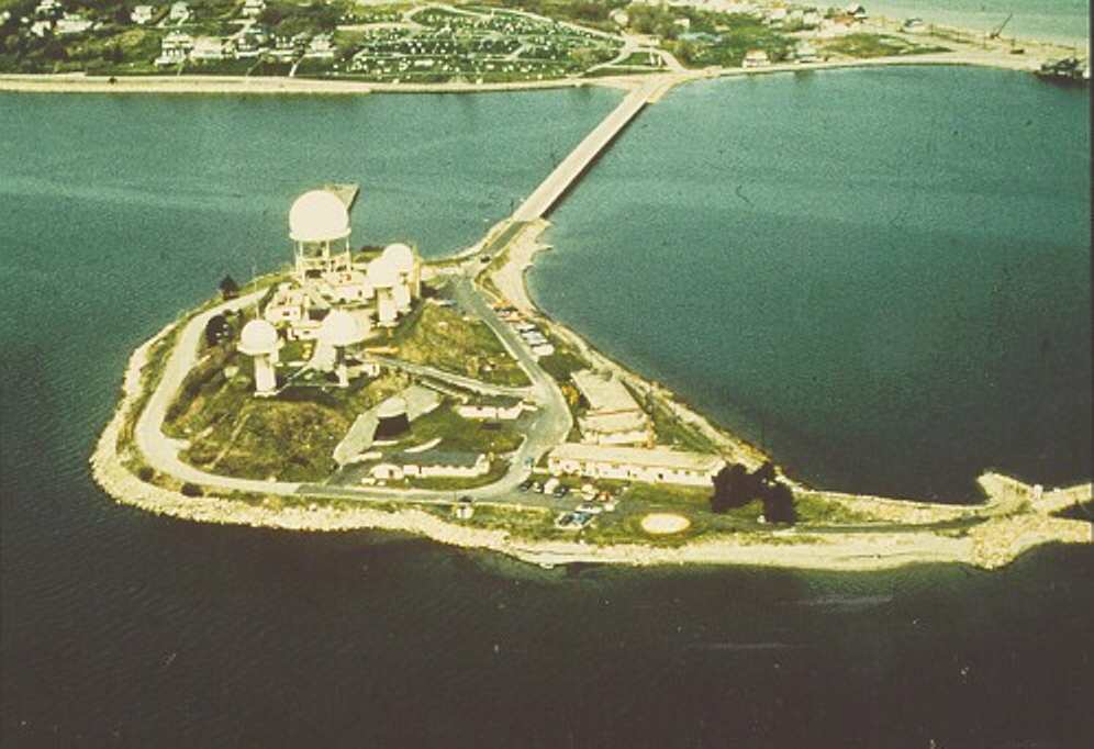
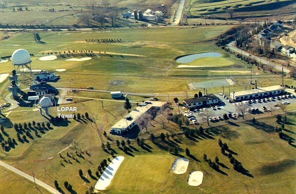
| Rockville Nike IFC Site W-92 Hercules (TRR and HIPAR), from Tom Page, 100 K Bytes |
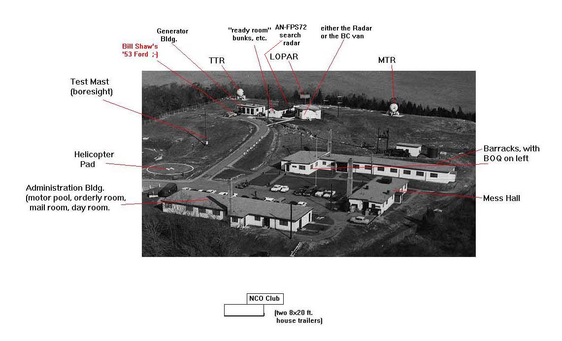
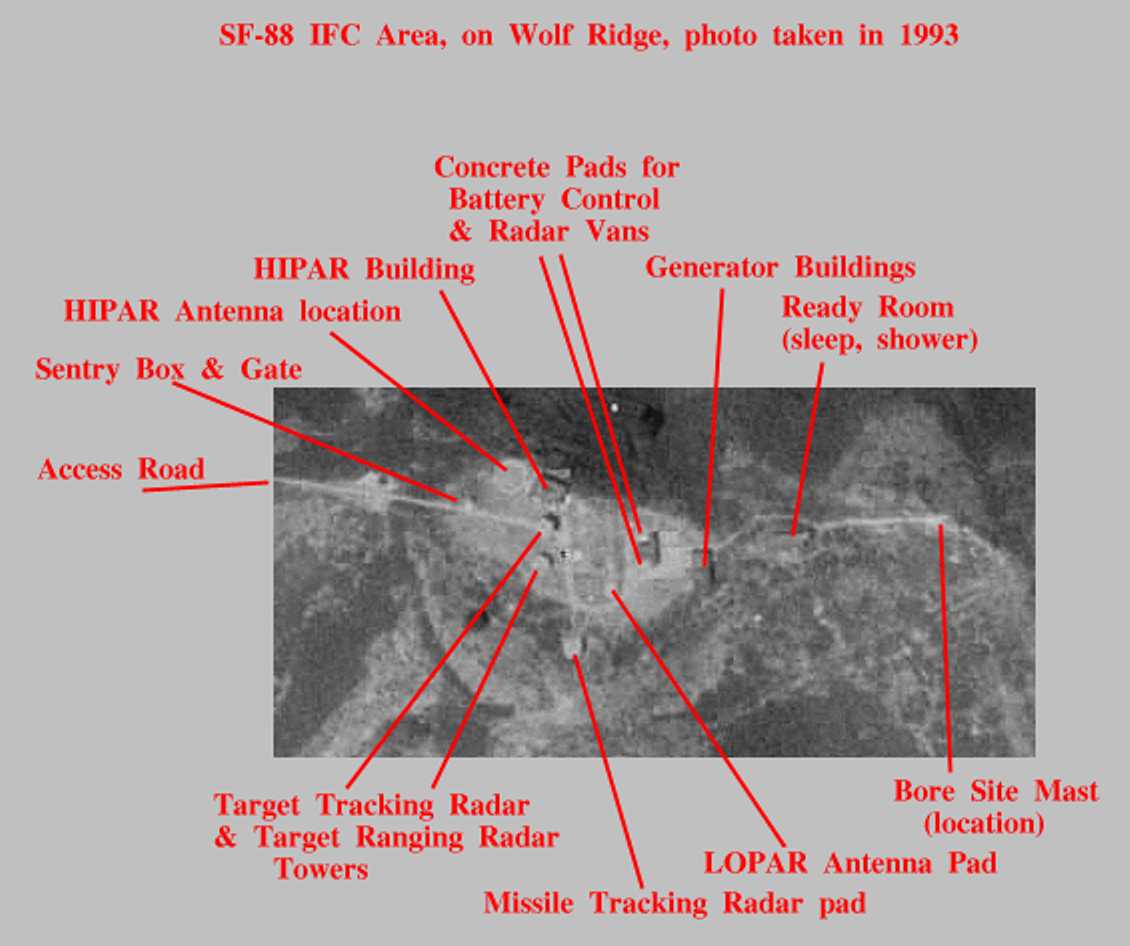
Annotated aerial image of SF-88 IFC Area (taken in 1993) 50 K Bytes
Many IFC areas were about 7 acres in size.
There were many variations.
From Bud Halsey
"... The overall size of
our site (SF-88) is: ... IFC approximately 7 acres ...
factors that affect the overall size of the
Nike sites include the terrain and the location (sites in expensive
suburban areas were intentionally made smaller to hold down the cost of
buying the land). ..."
To help succeed in the above mission, the IFC area:
A few sites (often one in each defense area) had a
Training Trailer (T-1)
from Donovan West, zdf 33 - Feb, 2006
|
|
Because the earth is quite spherical ("round"), the higher you are above the surface of the sphere, the more surface and air above that surface you can see.
The radar waves used by the Nike system travel in quite straight lines, like light. (Some other lower frequency radar waves have somewhat more complex possibilities.)
A rough formula for the maximum distance that a radar wave transmitted from a given height will touch the ground (horizon) of a smooth earth is:
| Height | Distance to horizon |
| (in feet) | (in miles) |
| 10 | 3.9 |
| 30 | 6.8 |
| 100 | 12.5 |
| 300 | 21.6 |
| 1,000 | 39.5 |
| 3,000 | 68 |
| 10,000 | 125 |
| 30,000 | 216 |
In fact, you can add the range due to the height of the radar to the range due to the height of the aircraft. For example, if a radar is 300 feet high (range 21.6 miles) and the aircraft is 1000 feet high (range 39.5 miles) and the earth is smooth, add the 21.6 miles and the 39.5 miles and get a possible radar range to that aircraft of 61.1 miles.
The above also assumes the radar is sufficiently powerful, not being jammed too badly, and many other happy factors.
Then there are factors such as defraction and atmospheric bending that can extend the effective range somewhat beyond the numbers given above. Welcome to the scientific black magic of radar.
And sometimes there is no tall hill. "My" Nike site, in Chicago next to Lake Michigan, was on a little rise maybe 15 feet above the water. Later the radars were placed on towers.
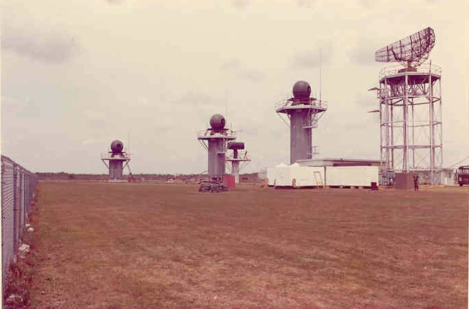
and if there is no hill, use towers
|
You put your antennas onto tall towers ;-))
These are Ajax antennas at Fairview Park ( CL 69 ) Photo from Dick Barth |
|
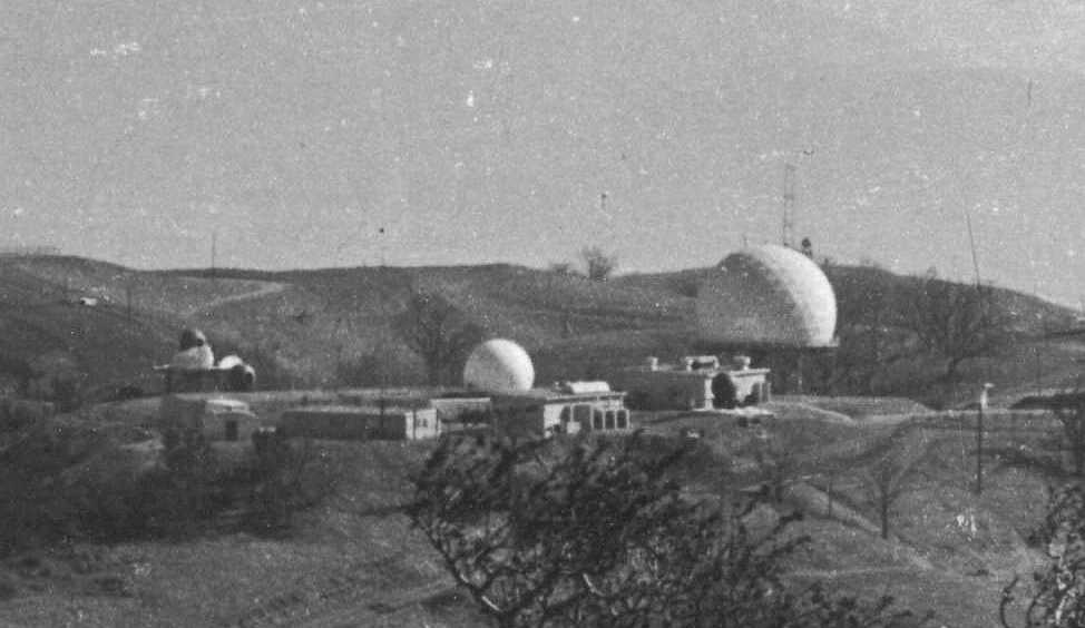
Site HM-69 ( Everglades NP )
From Left to right: Missile Tracking, Target Tracking, LOPAR Acquisition, Target Ranging Radar (40’ tower), ABAR Acquisition Radar Photo from Ted Swanson |
| 
| 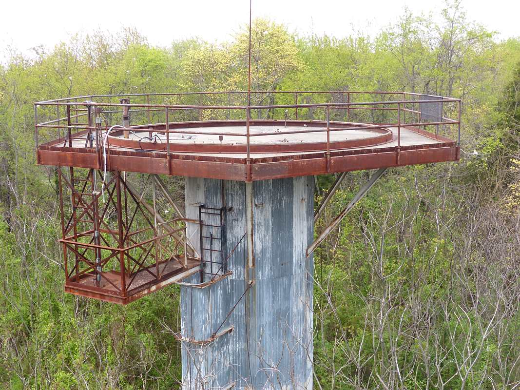
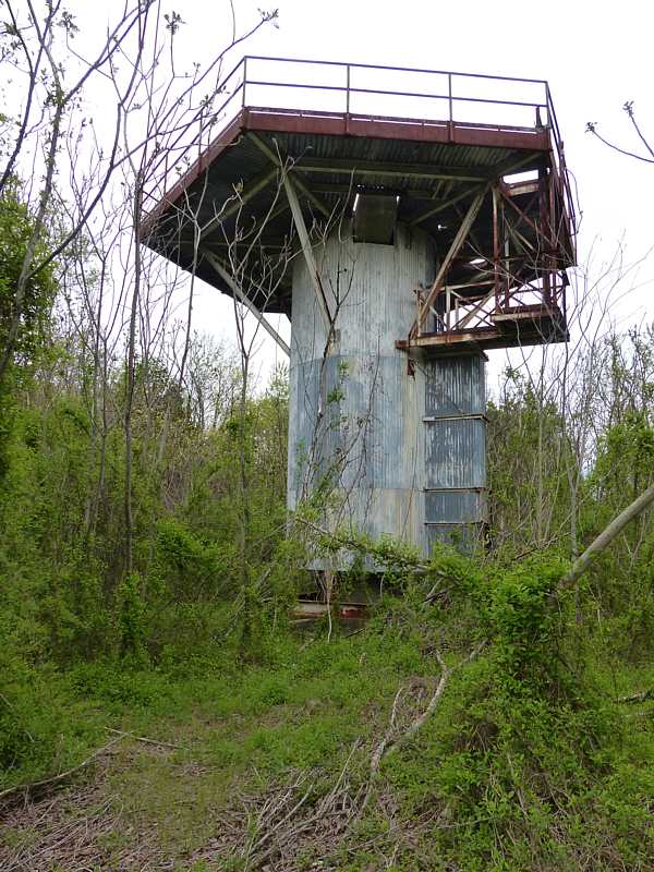
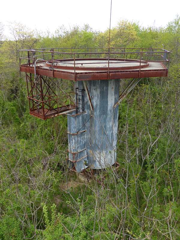
| The towers get the radars above surrounding buildings and trees.
In their active life, there were sun-shades around the tower to reduce differential expansion which causes tilt. Photos of PH-58 in 2015, by Larsen, David A. Also see SF-88 here |
In part, this fence was to keep roaming cows, boy scouts and other casuals from interfering with operations. Occasionally (maybe once a year) tours were pre-arranged. Families, boy scouts, mayors and other interested or influential people were carefully escorted (after classified displays or information were covered or otherwise hidden.)
In general there was one gate (for the access road) through the fence, past the guard house. This was manned by an armed guard anytime the gate was open. Life, the international situation, and the troops were quite serious.
There was also the worry of serious intentional interference coordinated with an air attack. Due to the exposed positions of the IFC areas, we could really only hope that no competent attack (physical or electronic) would occur. In Korea, small "suicide squads" would be (and are currently) infiltrated or landed which attack a specific Nike IFC area. In general, the defenses were/are successful.
The access road was required to:
In the typically hilly areas, the single lane road although not heavily used, (6 trips to the IFC/day might be typical) could be the meeting place for two vehicles. To reduce the chance that one of the two vehicles might have to do a rather dangerous back-down maybe a half mile, in the dark, in the fog, in a hurry (alert), with tired drivers, informal "road is busy" signaling systems were installed in many places.
Helicopters:
As the Nike system matured, and testing and supervision by the battalion and
group got tighter, helicopters were used to aid quick or surprise visits and readiness tests.
Also a badly needed part or specialist could be brought in from base support
much more quickly than via public and local roads. The safe consistent use of
helicopters almost requires a helicopter pad. Since asphalt is inexpensive,
some critical sites had two helicopter pads.
The Ready Room did not usually include 'food service' so to take advantage of army cooking you had to go back to the 'mess hall', unless an arrangement was made to transport food to the IFC area. (We made "arrangements" with the cooks for C-Rations, and could live for weeks on that rather limited diet.) The local pizza drivers made a killing off of us.
Our Ready Room did not include showers, so those that wished to live for weeks at the IFC area (avoid inspections, administrative stuff) could smell rather ripe. Occasionally a word (or two) was required.
Drinking water was supplied freely, often converted to coffee that "you could stand a spoon in".
The ready room was divided into an area for about 20 bunks, and a lounge area with scrounged chairs and old magazines. We hung blankets between the two areas so that the sleepers would not be bothered by the readers.
We got a hold of part of a bowling alley and some junk file cabinets and made a work shop in our lounge area. We could build HeathKits, tinker with radios, do nerdy things. The ready room was heated with a kerosene heater. The generator operator was in-charge of that.
Our latrine was your basic two hole "out-house", and in windy Chicago winters you could really chill your butt.
The Nike system was made as light as practical for easier transportability. Motors and transformers using 400 hertz (cycles per second) electricity are considerably lighter (need less iron) than similarly rated motors and transformers for 60 hertz. Also 400 hertz is frequently used by the Army and Airforce in aircraft situations.
Most commercial power is 60 hertz (U.S.A) or 50 hertz (Europe). Special equipment is required to do this conversion - usually a 60 (or 50) hertz motor direct coupled to a 400 hertz generator.

| If commercial power is available, except for alerts, the site can use converters to make 400 Hz for 60 Hz. This saves gasoline and wear and tear on the gasoline (or desiel) generators. To switch from converter to generator takes some method of synchronizing the phases and voltages before switch over. |
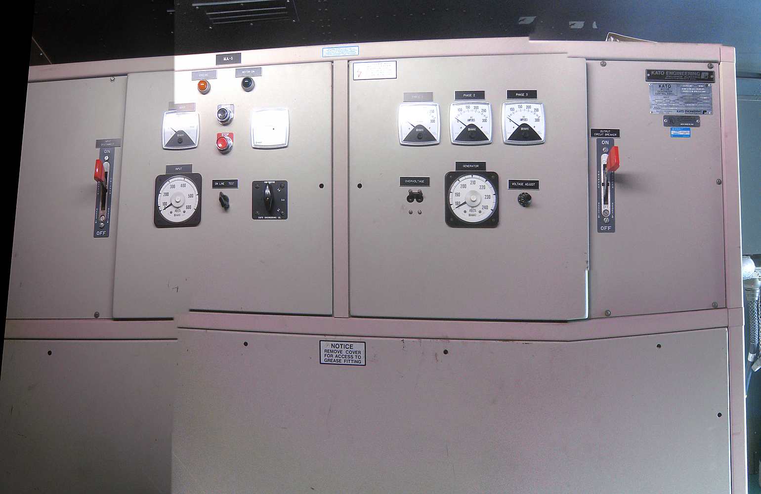
| 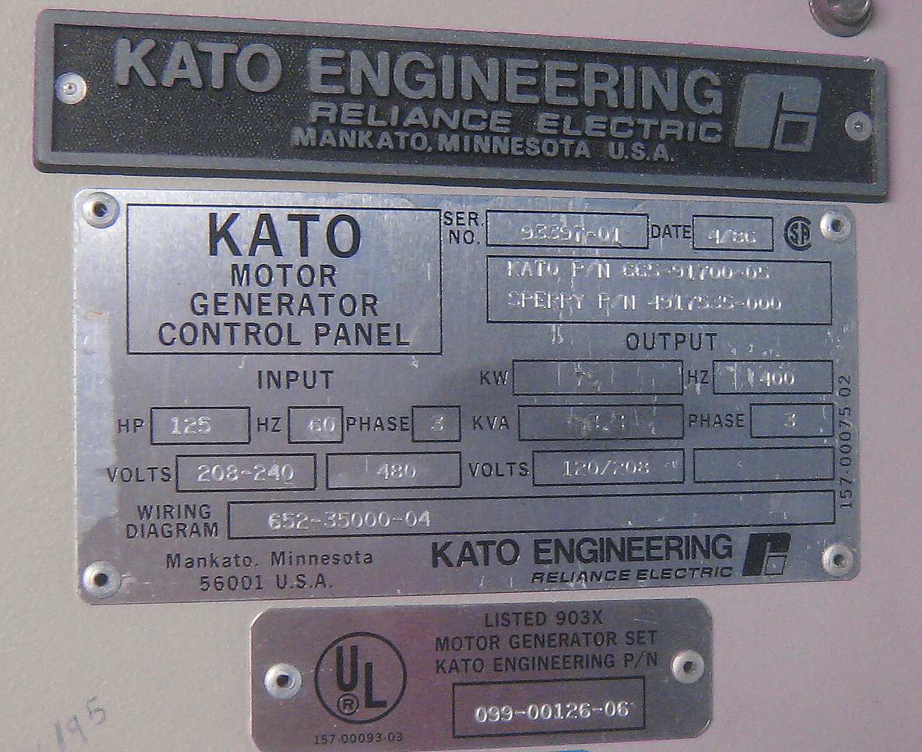
| The converters shown here are not vintage equipment, but secured surplus from AT&T to run equipment at SF-88 (somewhat restored) |
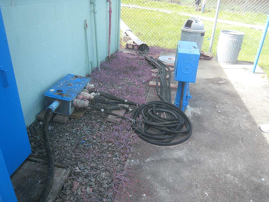
| This is the current SF-88 IFC power distribution box and cables. The frequency converters are to the left - inside the green wall. |
In the case of an alert, both the launcher area and IFC area started their generators, and switched over to this power. The commercial power was subject to a number of possible situations such as normal outages, attack damage, or intentional disruption.
|
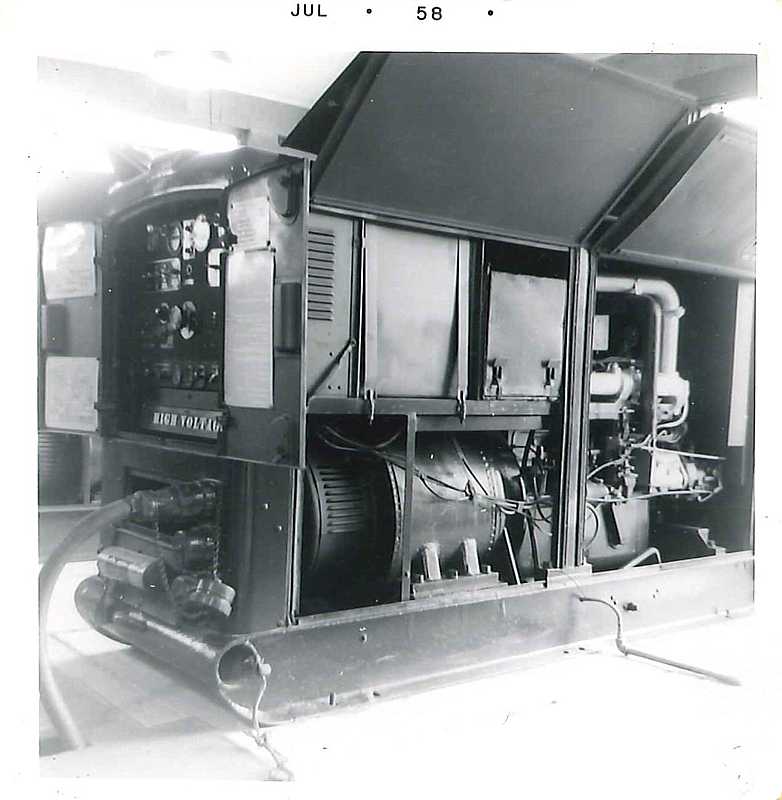
With the Nike Ajax, we had two gasoline engine driven 40 kW generators, and an operator
to watch them.
A 400 Hz 40 KW generator fits well into a two wheel trailer, and is a little larger than the
usual search light generator you see at store openings. An engine working at 40 horse power
easily runs a generator running at 40 KW, even allowing for the usual generation losses.
Photo from Dick Barth Fairview Park ( CL 69 ) |
The Nike Hercules HIPAR radar and associated equipment increased the power requirement and those sites had larger generators enclosed in buildings.
There was a necessary link with the launcher area that provided the following necessary information:
E-mail from Carl Durling
|
Hi
I served at a fixed Nike site on Okinawa (Naha AFB) in 1960-61, and a mobile unit at Fort Bliss Texas. At many fixed sites where there was a security or safety issue there were "tunnels" consisting of 3' to 4' "pipes" in which the cables were strung that connected IFC electronic equipment to Launcher area equipment. These cables were up to a mile long (the usually minimum distance between the missile and the missile tracking radar necessitated by the limiting "tracking" speed of the radar equipment). On Okinawa, Site 8 (Btry D) protected Naha Air Force Base. The IFC area was on one side of the runway, with the Launcher area on the other. The "tunnel" was about one mile long. I was told that personnel inspected the tunnel using "coasters" of some kind, never actually saw the tunnel except the entry point on our IFC site. For our mobile units, we had to "string" these cables manually, and would bury them for security reasons. Many people don't realize that there was a physical connection between the two elements of a missile site. It was not all electronic, including communication. Carl Durling |
|
Where I served - Chicago water front park area mid 1950s - there
was no tunnel for the IFC to Launcher area cable.
It is my impression that the signal cable to the Launcher area
was dug in using a motorized trench digger, like for your
water line to your house. There were indeed various challenges
along the way, like crossing under a major highway and
under/over several city streets. (The highway - Lake Front Drive -
did have walkthrough tunnels for park visitors (and soldiers) to
get under the big road. For some reason, I was not concerned!)
I thought we were concerned about everything - but since we had radio contact with the launcher area and back up phone lines - Thinking back, by the time we arrived at the site, the cable had been laid, just like the water line and electric power were available. (The IFC toilet was an old fashioned out-house - like back on the farm. We did not use Porta-Potties ) In any case - there was no inspection tunnel for OUR cable - |
Phone links to the administration area were useful for arranging transportation of relief crews and other day to day requirements.
At the time that I was serving, the link to Tactical Headquarters was usually faulty, and Tactical Headquarters seems remote or non-existent. We arranged phone links through commercial channels with adjacent batteries.
During the 1955-56 alerts we happily tracked airliners and private planes (there was nothing else).
412 Target Designation System
There was an empty place in the corner of the BC Van behind the Acquition Operator
that rumor said was to be a "412" communication unit to enable "Tactical Headquarters"
to make displays on our scopes indicating which targets to shoot at. This had not
arrived by February 1957 when I returned to civilian life.
In Aug 2010 Jim Tarbet sent the following
| I was trained on the AWCS 412L (AN/GPA-73 & subsystems) system that GE built for the Air Force in the early 1960's. The system used "high speed" and "static" logic whereby every pulse, every signal became resynchronized. Do you know anything about this? The HL circuits contained a holding circuit (delay line & loop) where the output was clocked through Ľ uSec after the input, thus always maintaining signal integrity. The SL circuits did the same, except the holding signal's polarity was reversed. This functioned essentially as a flip-flip (there were none in the machine). The system also used magnetostrictive delay lines as a "solid state" drum. Outside of the fans, and switches, there were no moving parts. The 412L was probably the first major integration of similar but disparate DP equipment. It was able to function in a networked environment without a general purpose computer. The Weapons Control Computer (AN/FSA-21) was optional, required only for mini-SAGE-type control of weapons. Are you familiar with any of this? Any help? Would you like to know more? I have attached a 4-frame PDF file [750 K Bytes - middle sections missing ?? ] that shows the general relationship of all equipment components. |
Our unit turned in a UFO report to the Air Force in the summer of 1956.
|
While I was on a three day pass, our unit reported an Unidentified Flying Object ( UFO ).
It was traveling very high (above 50,000 feet) at about 550 miles per hour.
Not at all like the usual propeller driven airliner.
(Most airliners way back then were piston engine or turbo-prop traveling much slower.)
According to the folks who tracked the object and wrote the report,
the object approached from the east, got almost overhead, then turned north,
and they lost it to the north at the limits of the tracking and acq radar scan limits.
I now wonder if a U-2 was the object of that UFO report. According to
Wikipedia
Of course, to most of us, most objects flying are technically "unidentified" ;-)) Unless you are at a government aircraft control facility ( FAA ) you often see just a dot and/or a con trail in the sky with no additional information. We are seeing a "UFO" ;-))
The military is of course VERRY interested if an aircraft, "identified" or not, is Friend or Foe.
|
Later there was sophisticated and effective control using:
Ron Loving provides the following:
The Army ADA batteries were always under the command and control
of the Air Force by several means. Then came the Army command and
control from the Army Air Defense Command Post (AADCP) at the
battalion level. You might lose communications with the Air Force but
your battalion still had control of you.
During the time of an air battle, a pilot could loose or forget to activate his IFF equipment. If so, there was only one safe way to return to any air base in any area. That was through the SAC-EWO safe corridors. The Strategic Air Command had predefined safe corridors back to any Air Base if the aircraft was having IFF or other problems. These corridors were zig-zag lines (not straight lines) that the pilot had to follow and he had to be at certain altitudes at any given range to the air base. These safe corridors were marked on the PPI scopes in the fire control vans of HAWK and NIKE batteries . As long as an aircraft was in the corridor and heading in or out and at the proper altitude for the range he was at, he was safe without squawking the proper IFF code or no code at all. If there was an air battle going on at the time, most stray aircraft coming into range of a HAWK or NIKE battery would have been taken out, just because.
In Alaska the Air Force interceptors would have engaged any low flying aircraft. High flying bomber formations were at the pleasure of the NIKE batteries.
The unofficial motto of ADA was to "shoot them all down and sort them out on the ground" and then send out letters of apologies.
Ron
The Integrated Fire Control (IFC) area had one or more surveillance radars for target identification. These are also called "acquisition" radars.
In the original Nike Ajax sites, there was what is now called the LOPAR (for LOw Power Acquisition Radar) acquisition radar with a maximum display range of 100,000 yards or 56.8 miles. This was a "normal" magnetron pulse radar with a switchable moving target indicator (MTI) option. Nothing very fancy, just like you read about in the text books. 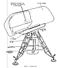
Hercules sites (with the much longer missile range) needed a much longer range surveillance radar.
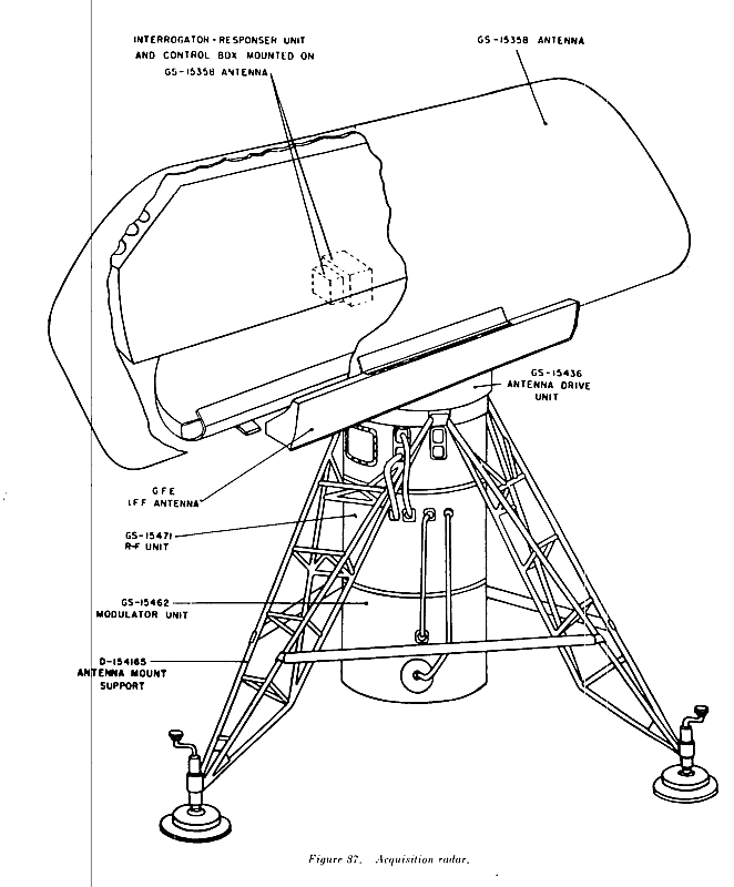
Two general types of longer range surveillance radars were supplied:
- the very large HIPAR radar that had a large control building. There was very sophisticated pulse generation, and multi-channel receivers with unique moving target indicators (MTI) and great deal of anti-jamming capability.
- or a less sophisticated "Alternate Battery Acquisition Radar" (ABAR) radar usually either AN/FPS-69,-71 or -75.
Hercules sites also usually had a LOPAR radar. For more information "right now", you may jump ahead to acquisition. (Use the "back" function to return here.)
The Integrated Fire Control (IFC) area had radar(s) for target tracking (one target at a time)
The Nike Ajax used one Target Tracking Radar using a fresnel lens focusing technology.
trailer
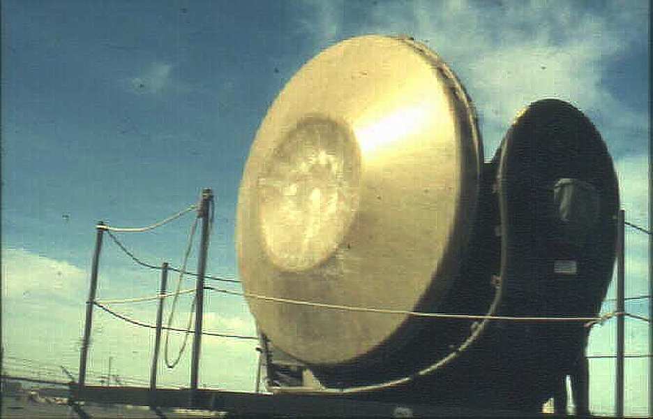
consoleThe Nike Hercules used two Target Tracking Radars. Both radars used a cassegrain (folded optics) technology using 2 reflectors. One radar tracked the target in azimuth and elevation, in "X" (3 cm) band. The other radar (Target Ranging Radar) tracked the target in range, in several radar bands. Range jamming is easier than angle jamming, so great attention was paid to counter-acting the range jamming including band switching, very agile frequency changing, pulse blanking, and pulse repetition rate changing.

Nike Hercules Target Tracking Radar (TTR) (image is 33 K Bytes) (Photo credit Rolf Goerigk)
For more information "right now", you may jump ahead to Target Tracking Radar. (Use the "back" function to return here.)
Depending on the local topography (and trees) zero or more of the other radars was on a tower. There were several generation of towers, and their heights seemed to be standardized in multiples of 10 feet.
See Survey of Former Nike Missile Sites In New Jersey and Tower for Tracking Radar, Nike site NY-80C, Riker Hill Art Park, Livingston, NJ. by Don Bender for examples of these.
See Abandoned Radar Site (view east toward gate) for example images on the west coast.
The following is from Don Bender
|
If the tower is a bare concrete pylon surrounded by an outer steel skeleton
(square in plan view if you were looking straight down on the tower), then it's
an early tracking radar tower.
If its a concrete pylon, covered by corrugated metal directly surrounding the circular pylon, and has an upper deck supported by cantilevered arms extending out from the central pylon, then, it's a late model tracking radar tower. Some old acquisition radar towers were triangular in plan view (viewed from above). The HIPAR tower was HEXAGONAL in plan view, as was it's concrete foundation structure. That's the easiest way to identify it. It had 6 vertical steel posts running up vertically from the foundation (one at each of the six corners) and the whole affair was a sort of a tubular steel space frame which permitted relatively easy disassembly. In my experience -- here in the New York Metro Area -- most of the HIPAR towers appear to have been removed from the sites. An easy way to "ID" the typical HIPAR tower, is that it does NOT have any central concrete support column or pylon -- it is a metal space frame structure, and it is hexagonal in plan view (looking straight down, from above) an important recognition feature. At sites where the HIPAR tower was removed, you can often locate the hexagonal foundation or footings. These vary somewhat from site to site, although they are all hexagonal in plan. They are normally located close to the HIPAR Equipment Building. |
This computer received tracking inputs from the target and missile radars and provided the following:
The Integrated Fire Control (IFC) area had a computer to aid target selection, aid launch timing, send missile commands. It was in the Battery Control van behind the Battery Control Officer. 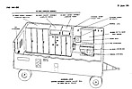
- During pre-launch, while tracking the target, a Predicted Intercept Point and a Predicted Time of Flight was presented on plotting boards to the Battery Commander. This was based upon an assumed straight line flight. It was up to the Battery Commander to try to evaluate what the target would really do, and decide when and if to FIRE (launch a missile).
- After launch, all of the above were continuously updated for the Battery Commander, and the computer also sent guidance commands to the missile via the Missile Tracking Radar.
- The missile burst command, also via the Missile Tracking Radar.
The computer technology was "analog" instead of the digital technology which was quite primitive and unreliable at that time. For more information "right now", you may jump ahead to computer. (Use the "back" function to return here.)
The battery commander sat in the Battery Control van with: and was in direct communications contact with:
- the target tracking operator(s)
- the missile tracking operator
- the Launch Control Officer(s) in the launcher section(s)
- and Tactical Headquarters
and operated the "FIRE" switch to control if and when to launch a missile
He was the person responsible for the whole operation, and of course, received training for this function.
The missile tracking radar physically and electrically resembled the target tracking radar except for the dual transmit pulse capability. The missile tracking radar also transmitted the missile commands
trailer
console
For more information "right now", you may jump ahead to Missile Tracking Radar. (Use the "back" function to return here.)
The Integrated Fire Control (IFC) area had a radar alignment system for "bore sighting" the tracking radars
This was located about 200 yards away from the tracking antennas (sometimes in a separate fenced area.) We posted a guard there at night, extremely lonesome, boring, unpleasant duty (no guard house, no light) - finally abandoned guarding the area. 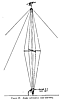
The system included, a cable for remote control and power, a tall mast with supporting lines, a control box (1'x1.5'x1.5') mounted on the mast, a waveguide up the mast, a little horn antenna and cross arm optical targets on the top of the mast. This was used primarily for boresighting the tracking radars.
Basically you wanted the radar beam to be aligned with the optical axis which had to be aligned with the sine/cosine potentiometers which (when driven by range information) yielded height, north_south, east_west information for the computer and plotting boards.
There was also provision for testing the radar receiving sensitivity.
For more information "right now", you may jump ahead to Alignment. (Use the "back" function to return here.)
For more info look at Digest . Warning - this is in the middle of a 150K byte file.
Rolf Dieter Görigk has some great T-1 photos at this T-1 web page and some jamming information.
The following information from Greg Ramsey greram@caro.net
|
The T-1 was a modern trailer about forty foot long. It was definitely more modern in that employed transistor technology instead of tubes although the amplifiers were tube driven. Due to the advent of transistors, there was also air conditioning! Three good sized AC units insured that temperatures remained stable and also according to the manuals, NBC filters were available that could be mounted on the AC units. (Question) I heard it was operated by two men who did not mix much with the general population. I was a 24Q with a G2 skill identifier and was responsible for the maintenance. Furthermore, a 16C assisted me with checks and actually running the training missions. As to mixing, well, we did kind of stand apart from the rest of the crews and maintenance teams. (Question) I heard that it gave operators a good workout The T-1 was capable of simulating up to six aircraft to the BC and RC van's radar crews. Each individual simulated aircraft was produced by a TCG (Target Coordinate Generator) and various parameters were controlled including; velocity, bearing, range, altitude, aspect ratio or reflectivity, rate of ascent/descent and video on/off/mom-off. The mom-off setting allowed us to actually remove the video presented to the radar crews simulating a super-stealth capability well before it's introduction. Additionally, the T-1 would provide a simulated missle for engagement, a full complement of ECM, both passive chaff and active spoof, IFF and passive interference such as ground clutter. And this was all accomplished without the need to turn up the first radar emission.
Actually, there were panic switches available that would remotely
release the cables from the BC and RC vans. This was not recommended
due to the possibility of damage to the connectors. The connectors
themselves had quick release arrangements so that they could be
manually disconnected very quickly by simply pulling a lanyard on the
cable heads.
(Question)It went from site to site?? or people from an
area went to it???
A)
Originally, it was apparently to be used on a temporary basis with it
traveling from site to site. I think there were somewhere around a
hundred T-1's produced. While I was in Germany, there were still 4
battalions of 4 batterys and each battery had their own T-1.
I always answered the question of what I did in the military by
telling folks I got to play video games. And a lot of times, that is
exactly what it felt like!
Greg Ramsey
|
The following information from Mike Hinton mikehinton@tyler.net
|
Ed, I have just finished reading your account of Nike firings at Crete. I was interested in your comments about the T-1 trainer van. We used the T-1 both at McGregor and at Crete. We also used it extensively for training on-site. The T-1 was capable of simulating any type of maneuver/jamming imaginable. We hated to see them hook it up because it gave us a hell of a workout. Very effective training. By the way, I fired from both McGregor and Crete during the four years that I was active. Hope this helps. Keep up the good work!! Thanks Mike Hinton |
Newspaper Photo at Bill Evan's web site.
If you have comments or suggestions, Send e-mail to Ed Thelen
Return to home page,
Goto Next Section
Updated Jan 2, 2019
Return to top


