Go Back to Home Page
With the successful firing of Round 66 in October 1961 to prove the latest control system changes, the NIKE R&D System was prepared for complete systems test to begin in November. This chapter describes the NIKE System in the state in which it was subjected to the official system tests which marked the end of the R&D phase of the project. The tests themselves are summarized in the next chapter. For purposes of this chapter, it will suffice to mention that these system tests comprised the firing of 23 missiles launched under radar control-three against a ground target, all other against QB-17 drones in flight. Of the 23 missiles, five carried real warheads and the other eighteen merely pyrotechnic token charges.Terminating with Round 92 in April 1952, these tests dramatically demonstrated that the NIKE did indeed offer an immediately practicable solution to the problem of high flying invading aircraft.
As the name implies, the R&D System was designed for test purposes, with provision for instrumentation wherever possible; it was neither a quantity production design nor a fully tactical equipment. (The latter objective was the goal of the NIKE I version, which was getting under way while the R&D phase was still in its final stages.) How the R&D Test System was developed from the drawing board conception has been related in chronological sectionsof the foregoing chapter. It now remains to describe in greater coherence the major system components which were actually used in system tests during 1951-52. A good place to begin is with the physical vehicle itself.
Like all other components of the NIKE system, the design development of the missile and booster had been governed by the general philosophy of staying as close as possible to established techniques without departing from the original AAGM concept any more than forced by practical necessities. Of course, advantage was taken of the advances made in rocketry during the R&D period of theNIKE project, particularly in the direction of achieving reliability. While numerous refinements were developed in the course of the project and various alternatives were explored in the process, it is remarkable how many of the general features of the original proposal were actually retained. The most outstanding improvements concerned the booster which was drastically simplified; the shape of the fins to improve performance, stability, and controllability; and the warhead whose lethality was increased. Even with all these advances, the size and weight of the missile had grown but little. How the missile design has thus evolved from the original concept through various experimental stages to the actual test vehicle is summarized in Appendix 6 and illustrated in figure 12.
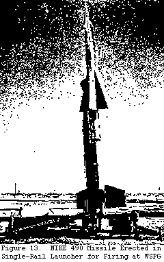
The missile-booster combination adopted for the system tests is shown in figure 13 (page 84). This was the so-called 4901 design and was identical to that of the missiles launched during performance tests (May 1950 to July 1951). The government-furnished booster employed a solid propellant motor delivering about 49,000 pounds of thrust. The booster gross weight was about 1,560 pounds.
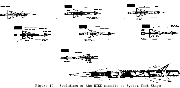
The boost phase lasted about three seconds, at the end of which the booster separated from the missile. The sustain phase was implemented by a liquid fuel motor of 3,100 pounds (lbs.) vacuum thrust with a burning time of about 71 seconds. The over all gross weight of the missile was 1,115 pounds, of which 300 lbs. comprised the propellant in the form of aniline-furfuryl alcohol as fuel, and red fuming nitric acid as oxidizer. This motor and the associated tankage are shown in the cutaway view of the 490 missile at thebottom of figure 12.
The design of the missile airframe shown in Figure 12 was dictated by considerations of drag, lift and control. The requirement of low drag resulted in a slender missile of 20-to-1 fineness ratio and in acarefully streamlined ogival {ovigal?} nose. The aerodynamic shaping of the nose was made possible by the fact that no data-gathering equipment need be carried in the missile for a command-type of system. The size of the wings was dictated by the 5g manoeuvre requirement and their shape by a proper compromise between lift efficiency and good drag characteristics. The small receiving and transmitting antennas shown aft of the control fins were likewise carefully streamlined for low drag. The missile was of a "canard"configuration with two pairs of delta-shape steering fins forward and with roll control effected by two pairs of trailing-edge ailerons onthe main fins.
The missile was roll-stabilized so that the computer could know the complete orientation of the missile in space. This required theuse in the missile of a free-free gyro whose orientation was set shortly prior to launch. Stabilization was accomplished through a hydraulic servo system with this gyro as a control element. Stabilization in roll was initiated shortly after separation of the missile from the booster.
Hydraulic servo systems were used to actuate the forward steering fins. The acceleration orders transmitted to the missile from the gyro, were matched to the actual missile acceleration by means of accelerometers appropriately placed in the missile itself. Difficult design problems were experienced with the roll control and steering functions because of the wide range of altitudes and velocities over which these functions had to be performed. Early accuracy studies indicated that fast response times were required for good "end game play" (response to acceleration orders just prior to intercept). To achieve such response times uniformly over the wider ange of flight conditions referred to, the gains of the servo control loops had to be varied accordingly. This, in turn introduced serious problems in stability of these loops. An intensive study of these problems led to very satisfactory solutions which involved the introduction of pressure pickups, rate and fin feedbacks, and carefully designed shaping networks in the servo loop.
Because of the command nature of the guidance, only a minimum amount of electronic equipment needed to be carried aboard.. Part of this equipment was required for receiving and decoding the acceleration orders transmitted to the missile from the ground; some electronic equipment was associated with the amplifiers in the control systems discussed above. Finally, a transponder was found necessary to assure firm radar tracking through the boost and turn-over phase of the trajectory and at extreme ranges where skin tracking would provide only a marginal signal.
Early theoretical performance estimates had shown that the NIKE Missile should best start its self-sustained flight at an initial velocity of 1,700 feet per second obtainable under the impulse of a fast-burning solid propellant booster rocket system designed to separate from the missile at the end of the boost by its own drag. Solid propellant rockets were obviously advantageous for their structural simplicity and adaptability.
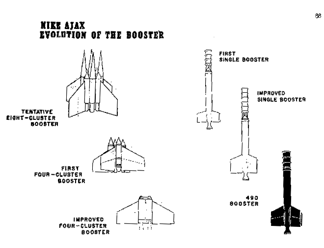
So long as no single rocket of adequate size was available, smaller rockets had to be combined in cluster arrays, as had already been proposed in the AAGM report. After extensive experimentation during the R&D period, the problems of achieving simultaneous ignition and thrust cessation, as well as clear separation of four rockets mounted in a cluster structure, were eventually resolved. Inthe mean time, however, a solid fuel rocket - the AlleganyT-39-3DS-4700 - large enough to serve as a single booster for the NIKE, became available in 1947. It had many advantages over the Aerojet cluster-type booster, in that it weighed less, it was easier to assemble, store, handle, and load, and it was smokeless and reliable. During the period June 1948 to May 1949, both the clusterand single boosters were flight rested in the NIKE field test programa WSPG. Beginning with the 484 test series in January 1950, the cluster booster was dropped in favor of the single-type booster which was later standardized and accepted for the system tests. The evolution of the booster to the system test stage is illustrated in Figure 14.
The last major component of the missile to be discusses here is the warhead and its associated equipment. The NIKE warhead was changed perhaps more radically from its original conception in the AAGM report than any other system component. The original warhead, which was to weigh 200 pounds. was meant to produce a slowly-expanding uniform disk of shrapnel, travelling along its axis with the velocity of the missile at detonation. Although models of this type of warhead tested by BRL performed satisfactorily, it was abandoned early in the program for three reasons. First, it would have been necessary to burst the shrapnel warhead well in advance of intercept, conductive to serious fragment drag and slow-down; second, the system was ill-adapted to an overtaking attack; and finally, new information suggested that small fast fragments possessed lethality over larger slower shrapnel.
Consequently, an analytic investigation, begun already in 1946, was pursued to determine the optimum values of those relevant parameters that were under design control. From this and related calculations, it appeared that an essentially spherical pattern of thirty-grain fragments impelled with a static detonation velocity of 7,000 feet per second would be nearly optimum.
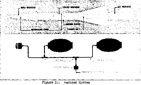
A total weight of 312 pounds was eventually adopted as a better compromise since system effectiveness seemed to increase rapidly with warhead weight up to about this value. To produce adequate fore and aft spray with a warhead in a single piece was recognised as extremely difficult. Therefore, three separate bombs were chosen -one smaller forward-firing bomb weighing 12 pounds to cover the nose sector and two identical barrel-shaped bombs weighing 150 pounds,each to cover 55 degrees fore and aft of the beam (see Figure 15). On the basis of an extensive design and test program conducted by BRL, bombs meeting these specifications were actually produced under the cognizance of Picatinny Arsenal.
All three warheads were detonated simultaneously upon command from the ground through a primacord harness running the length of the missile and branching off at the warhead sections, as shown in Figure15.
For reasons of safety, a provision was made to destroy the missile in the event that radar tracking was lost or purposely terminated. This was accomplished by a separate signal circuit in the guidance section which is automatically triggered by the absence of radar pulses for a prescribed length of time. The safety and arming device, designed and manufactured by Frankford Arsenal, became known as the T-93 Arming Mechanism.
Only five of the system test missiles (491 model) were equipped with high explosive, live warheads. On the other rounds (490 model)a spotting or token charge was carried instead of the warhead in order to mark the space point where a warhead would have detonated.
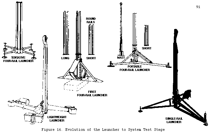
Associated with the missile at the launching site is a certainamount of auxiliary equipment in the way of launcher, loading facilities, and pre-flight checkout. The nature of the launcher used with the 490 missile in system tests is shown in Figure 13. The evolution of the launcher to the system test stage is illustrated inFigure 16.
All equipment for the system tests was experimental and preceded the design and development of the NIKE I tactical units.
The above is a brief description of the vehicle and its associated gear. The succeeding portions of this discussion are concerned with components of the ground guidance installation; namely the radar andcomputer.
The radar is the intelligence apparatus of the NIKE system. At the outset, it was evident that the accuracy requirements imposed onthe tracking radar were so stringent as to require an intensive radar development program. Since the accuracy of the standard lobing radars developed during the last war were limited by rapid pulse-to-pulse fading, it was decided to go to a system which would provide an independent measurement of angular error on each pulse. The successful development of the monopulse tracking radar system forNIKE represents one of the major contributions of the project to the fire control art.
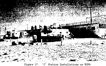
The two tracking radars which resulted from this development program are shown in Figure 17, installed at "C" Station, WSPG. The missile tracking radar is in the foreground; the target tracking radar in back. In the end of the building behind the missile radar is the computer. The antennas on the roof were used for safety tracking.
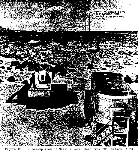
The target and missile radars are almost identical except for the fact that the missile radar includes the communication circuits for properly modulating the pulse train in accordance with the order signals from the computer. A close-up view of the missile radar isshown in Figure 18. The intelligence is conveyed to the missile via the missile radar beam by frequency modulation of the pulse repetition rate of the same train of pulses which is used to provide angular and range data on the missile position.
From a logistic and tactical point of view, it was found simpler to site the two tracking radars separately. It was therefore necessary that the two radar mounts be leveled and the radar beams boresighted with good precision. The requirements on boresight and on tracking accuracy led to the design of precision mounts for the radars and the installation of associated optical equipment for purposes of easy and accurate boresight adjustment. The high accuracy requirement led also to the demand for a highly precise data-transmission system to carry the tracking information from the radar antenna mounts and range unit to the computer. The data transmission developed for this purpose was accurate to 0.1 of a miliradian angle and to one yard in range.
The final system component to be discussed is the computer itself. The three major elements of the NIKE system - the missile, thetracking
radars, and the computer- comprise what is known as a closed-loop control system. The basic purpose of the computer is to determine,from radar-derived target and missile position data, information required to guide the missile so as to intercept the target and to initiate a burst order at the most lethal instant. It operates to control the missile, bending its flight path from the nearly vertical launch onto a ballistic trajectory through the predicted intercept point; thereafter correcting the missile's flight whenever it deviates or when the continuously recomputed intercept point is displaced for any reason. These functions are divided into four mainphases - Pre-Flight or Pre-Launch Computation, the Turn Phase, theSteering Phase, and the Burst Computation. The full scope of the computer operation can best be described in terms of a typical NIKE engagement.
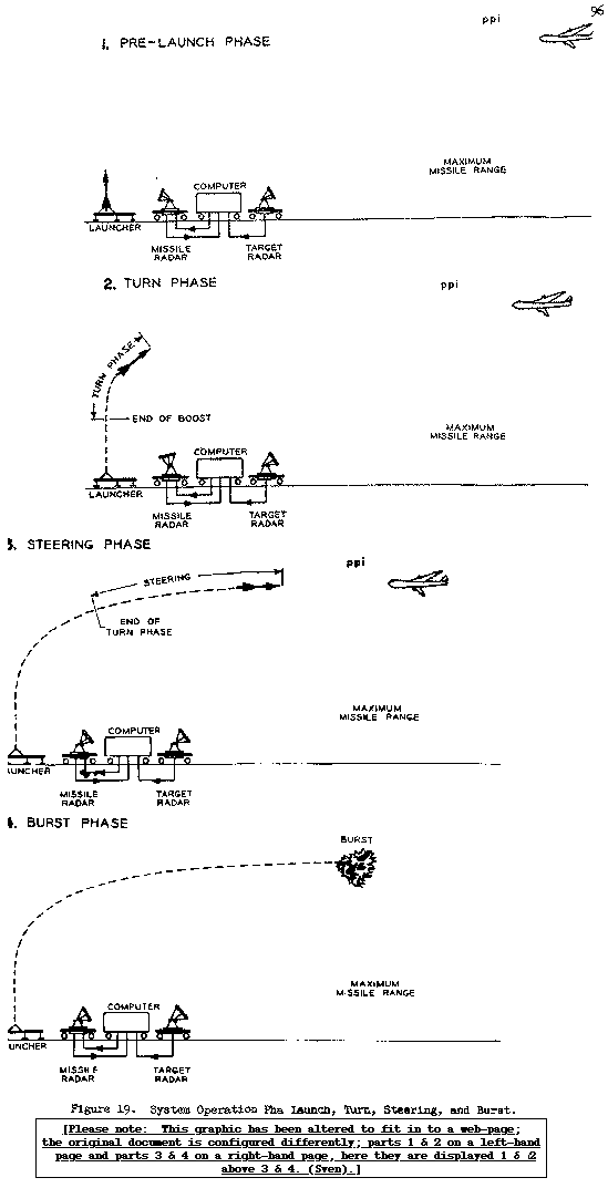
In Figure 19, a schematic picture of the NIKE R&D System isshown. A target tracking radar has, for some minutes, been tracking a designated target and furnishing information to the computer on theground. Prior to the launching of the missile, (Pre-Launch Phase),the computer uses the known missile ballistics and the target information transmitted to it by the target-tracking radar to compute a tentative predicted point of intercept (ppi). This procedure is similar to that employed in an antiaircraft gun director2. The predicted intercept point, together with other information obtained in its computation, is used for two purposes. First, it provided the tactical control officer with information which will allow him to evaluate target threat and to assign missiles to the targets intelligently; second, it provides information whereby a tentative plane {plan?} of action can be determined for positioning the free-free gyro in the missile. The target's present position and the ppi are continually displayed on plan and vertical plane plotting boards as an aid to the control officer in determining a suitable time to initiate the fireorder3. The time required to initiate this computation after target acquisition is small (about five seconds). Once a missile is designated, its gyro is continuously positioned as a function of the computer's most recent information on the predicted plan of action. Consequently, the designated missile is in a continual state of readiness, and its gyro axis is frozen only upon the initiation of the fire order. This condition corresponds to the Pre-Launch Phase illustrated in upper left block of Figure 19.
Once the fire order has been issued and the missile has been launched, the turn phase begins, as shown in the lower left portion of the figure. Immediately after the missile and booster have separated and after roll-stabilization has taken place (about five seconds total after launch), the computer issues a hardover turnorder in the general direction of the predicted point of intercept. This order is maintained until the computer observes that the missile is on a ballistic trajectory through the ppi. Throughout the turnphase, the ppi is being continuously recomputed to make the missile heading at release as accurate as possible. When this moment arrives, the turn order is removed and the turn phase thus brought to an end.
The job of the computer in the Steering Phase (upper right block of Figure 19) is two fold; first, to compute increasingly refinedversions of the ppi; and second to issue orders to the missile which will bring it to this point at the termination of the flight. It continues to compute correction orders made necessary by the fact that the ppi may change either because of the increasing accuracy of the prediction processes, or because the target may have manoeuvred.
The computer orders, as received by the missile via the radar tracking beam, must correspond with the missile's pitch and yaw planes. Consequently,the computer must at all times know the orientation of these planes. This knowledge, it in fact, possesses because it knows the heading of the missile and the nature of the constraints imposed by the roll-stabilization system. Computer orders are sent in the form of accelerations which the missile then proceeds to obey.
Before turning to the final phase of the computer operation, a brief word is in order on the nature of the system performance during the last few seconds of steering. The guidance system described so far is known as a closed loop system- a highly complex servo loop,the last link of which is generally referred to as the "end game" (the last few seconds before intercept). At this point, precision accuracy of the guidance system is extremely important, for it could mean the difference between a hit or a miss, success or failure. Associated with any servo loop of this type is a "gain" which is under the designer's control and which is a measure in some sense of the violence of the system's response to disturbances. These disturbances are, in the present case, occasioned by changes in thepredicted point of intercept. In turn, they may be legitimate disturbances incident on target maneuver, or they may be spurious disturbances caused by the presence on noise in the input data. Accordingly, there is the classical smoothing problem of suppressing noise without at the same time suppressing knowledge of legitimate disturbances due to target maneuver. It is possible to smooth the noise very heavily in the early portions of the flight, since there remains a great deal of time and adequate maneuverability margin to counter any maneuvers on the part of the target. This smoothing is highly desirable because over-scrupulous attention to noise results in a series of small maneuver oscillations of the missile which, inturn, exact a heavy penalty in induced drag. During the "end game" a heavy maneuver on the part of the target can tax the system severely,and could in fact, defeat the system entirely should it not be immediately recognised and countered. During this phase, heavy smoothing of noise is not possible, since this would tend to obscure the presence of target maneuver. To provide optimum balance between the effects of noise and those of maneuver, a system of data smoothing is used. In this system, optimum smoothing, as well as servo "gain", is appropriately varied as a function of the time-to-intercept.
Finally, at the appropriate time before intercept, the computer issues a burst order to the missile (see burst phase, Figure 19).The computer has stored in it information which would allow the choice of burst point to be made on the basis of many different variables, such as time-to-intercept, missile velocity, relative aspect of the missile and target, etc. An early study, however,indicated that a satisfactory solution to the choice of burst point could be made on the basis of time-to-intercept alone. Whilst a burst point at zero time-to-intercept would prove very satisfactory, it was found that a slight "bias", specifically a burst about ten milliseconds before zero time-to-intercept, had definite advantages in system lethality.4 But in order to assure that the warhead in fact detonates at the chosen point inspace, the computer must take into account various system delays and must issue the burst order somewhat in advance for the physical burst to occur at the desired instant. These various delays are all small and quite constant. The command burst plan for system tests had associated with it a flexibility permitting easy adaption to any new type of warhead which might be used in the NIKE system.
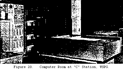
So far, the computer has only been discussed in terms of its functions. In Figure 20, the physical device itself is shown installed at "C" station, WSPG, for system tests. The project commander's position is between the plotting boards at the right; the guidance officer's position is at the left. The cabinets in front of the computer house camera for photographing the dials. When considering the complexity of its many functions, the size of the computer was remarkably small (although the later tactical version was considerably more reduced insize. 5
Footnotes for Chapter 4 - Description of the NIKE R&D testsystem
1. R&D missile designs were identified bythree-digit numbers, the first two of which referred to the year thedesign was initiated.
2. The main difference is that the accuracy of the gun director depends directly on the accuracy of its ppi computation; wheras in the NIKE system the pre-flight computation of ppi can afford to be relatively rough. Since the guided missile is controlled after launch, and therefore moderate errors in pre-launch intercept point may be corrected during flight, the accuracy required in this computation is considerably less than in the case of the gunfire director.
3. After launch, the same boards plot the target and missile present positions, thus giving a complete recordof target and missile flight paths during the engagement (seeplotting boards and computer in Figure 20).
4. On the average, it is desirable to have the target and the lethal (warhead) fragments run into each other, as happens when the burst occurs in front of the target, rather than with opposing velocities, as occurs when the burst takes place behind the target.
5. This chapter represents a summation of preceding Chap III and was based on references cited therein.
Go to top of Page
Go to Monograph Table of Contents
Go Back to Home Page