About These Ratings Difficulty: Beginner to intermediate Danger 1: (No Hazards) Utility:
Building a Sensitive Magnetometer and an Accurate Solid State Timer
by C. L. StongFebruary, 1968
ANYONE MAKING FIELD STUDIES of wild plants might want to mark out areas so that he could observe the spread or retreat of certain species over a period of several years. The area can be marked by stakes, of course, but if the stakes are large enough to be found easily among tall plants in summer, they run the risk of being accidentally knocked down or being pulled out by someone who does not know what they are for. Even short stakes become conspicuous in winter and invite destruction. Inoffensive bench marks can be installed close to the surface along fence rows or natural boundaries for locating points of interest by triangulation, but this expedient is both troublesome and time-consuming.
|
"My magnetometer is based on the effect a magnetic field exerts on protons in the nuclei of atoms of water. According to theory, most elementary particles including the protons in water-spin on their axes like tops. They are also magnetized. In the presence of a magnetic field, such as the earth's, the spinning protons precess around the direction of the field in the same way that a spinning top standing on its point at an angle precesses around the direction of the earth's gravitational field. The rate of precession is proportional to the strength of the magnetic field.
"Normally the protons are out of step with one another, so that their effects cancel and the precession cannot be detected. If, however, all the protons could be made to point in the same direction at right angles to the earth's field and were then released together, they would all precess together. The effect of all would add, and the precession would be easily detectable for a few seconds until the protons got out of step again.
"Unfortunately a magnetic field of more than a billion oersteds would be needed to line up all the protons at room temperature. This is much larger than the largest magnetic field ever produced. However, much smaller fields, which can be produced easily by a dry battery and a coil of wire, can cause slightly more protons to point one way than the other. The difference is sufficient to produce a detectable signal in the coil when they are released. The precession frequency, and hence the frequency of the signal induced in the coil, is about 2,025 cycles per second. After amplification it can be heard in an earphone as a musical tone about three octaves above middle C.
|

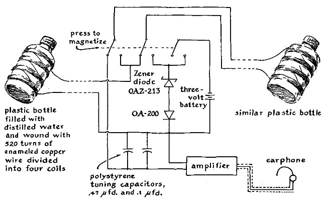
"The heart of the instrument is two plastic bottles wrapped with insulated copper wire and filled with distilled water. A switch of the push-button type enables me to connect the coils to either a three-volt dry battery or the input terminals of an amplifier. The bottles are mounted on the ends of a nine-foot pole at right angles to the pole, which supports in the middle the switch, battery and amplifier. Usually the coils are connected to the input of the amplifier. Pressing the switch transfers the connections to the battery. When the switch is released, the battery circuit opens first and other contacts transfer the coil leads to the amplifier [see Figure 1].
"At a potential of three volts the current in the coils develops a magnetizing force in the water of about 30 oersteds. When the field is turned off, the protons precess around the earth's field for about three seconds and induce an alternating voltage in the windings of the bottles. The windings are connected in reverse polarity. For this reason the induced voltages cancel if the earth's field is uniform in strength and direction at both bottles. Nothing is heard in the earphone except the residual noise of the amplifier.
"On the other hand, if the magnetic field differs at the two bottles, the induced frequencies also differ and a net difference in voltage appears at the terminals of the amplifier. Such differences are observed when one bottle is closer than the other to a buried magnet, a piece of iron or inhomogeneities of the soil. Beats or wavers then appear in the signal. They reflect the difference frequency of the current in the two sets of coils. The 2,025-cycle note from the earphone gets alternately louder and softer.
"The magnetometer can detect a minimum difference in field strength of about 3 x 10⁻⁵ oersted, but where I live the earth's field is disturbed more than this by differences in soil composition. The smallest difference that I can definitely identify as arising from a buried magnet is about 2 x 10⁻⁴ oersted, which gives about one beat per second. I bury permanent bar magnets that are three inches long and 3/8 inch by 5/8 inch in cross section.
|
"When I hear two or more beats per second, I know that I am near a magnet or some other object that exerts a strong influence on the earth's field. I then spoil the signal from one coil by placing a small piece of iron near it. The field at that bottle becomes so inhomogeneous that the signal fades abruptly. Then I hear only the steady signal from the second bottle. This signal also disappears when the second bottle is moved close to the buried magnet. By this procedure I locate the magnet to within a foot or two. It can then be found easily with a pocket compass.
"The magnetometer is inexpensive and easy to build. At a variety store I bought thin-walled polyethylene bottles 1 3/8 inches in diameter and 2 1/3 inches long with plastic tops. I filled the bottles with distilled water. Each bottle was wound with 520 turns of No. 24 Standard Wire Gauge enameled copper wire. (The diameter of the wire is .022 inch, equivalent to No. 23 American Wire Gauge.) Each winding is divided into four sections of 130 turns each. The sections are spaced uniformly along the bottle to minimize capacitance in the coils.
"The terminals connect directly to the push-button switch. The switch consists of the contact assemblies of three microswitches. The assemblies are mounted so that one plunger actuates all three assemblies. When the plunger is released, the battery circuit is broken and then the coils are reconnected to the amplifier.
"The signal from the coils amounts to only about 10-16 watt, equivalent to the radiant energy that enters the eye from a candle 16 miles away. The amplifier must therefore be of the type that develops high gain and little noise at the desired frequency of 2,025 cycles. It should also be compact and light, and it should impose a minimum load on the battery.
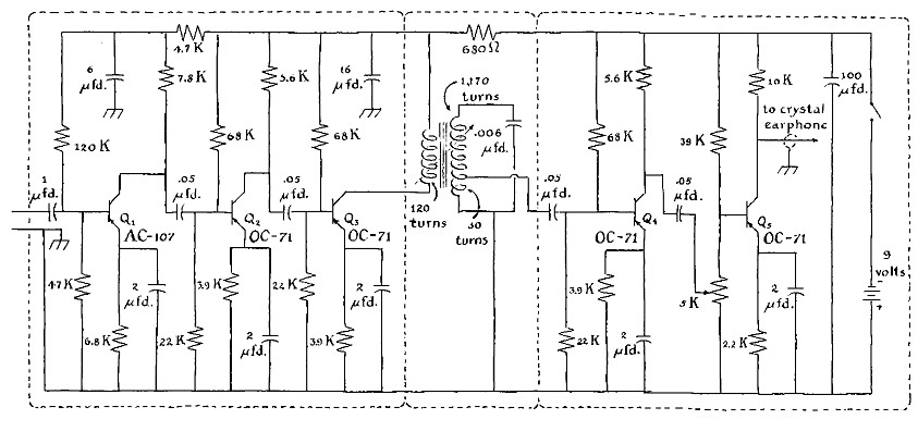
"My amplifier was designed around inexpensive germanium transistors. The first transistor of the string develops only about as much noise as is generated by the random motions of electrons in the copper coils. Noise is suppressed further by the insertion of a tuned transformer between the third and the fourth transistor of the string. The magnetic core of the transformer is of the 'pot' type: it has roughly the shape of a hollow doughnut equipped with a movable plug in the central hole. The torus contains two coils of wire, which are the primary and the secondary winding of the transformer.
"The unit passes only the narrow band of frequencies determined by the position of the movable plug and the tuning capacitor. The position of the plug is set by a screw adjustment to pass the desired 2,025-cycle tone generated by the protons. I use the Mullard Type LA2416 pot core, which I bought (together with the transistors) from Mullard Ltd., Mullard House, Torrington Place, London WC 1. Mullard is a branch of Philips' Gloeilampenfabrieken of Eindhoven in the Netherlands.
"The design of the tuned transformer is fairly critical. In particular the Q of the completed transformer–the ratio of the average energy stored in the transformer to the energy that is dissipated per 1/3.14 cycle–must be at least 160. Any pot core that, when wound, will yield this Q can be substituted for the Mullard Type LA2416.
"The primary winding of the transformer consists of 120 turns of No. 42 S.W.G. enameled copper wire; the diameter is .004 inch, equivalent to No. 38 A.W.G. The coil is wound first on an insulating form and covered by a thin layer of paper insulation. The secondary coil of 1,170 turns of No. 40 S.W.G. enameled copper wire, tapped 30 turns from the inner end, is then wound over the primary. (The diameter of the wire is .0048 inch, approximately equivalent to No. 36 A.W.G.) The secondary winding, when it is in place within the pot core, has an inductance of one henry and is tuned to the resonant frequency of 2,025 cycles per second by a capacitor of .006 microfarad. I used a capacitor that was made with polystyrene insulation to minimize the loss of energy and thereby minimize the width of the band of frequencies transmitted by the resonant circuit.
"A signal of 10-18 watt can just be heard above the noise of the coils and amplifier. The gain in voltage is about two million, so that certain parts must be shielded to prevent the amplified signal from feeding back into the low-energy parts of the circuit. I installed the amplifier and its nine-volt dry battery in a tobacco tin. The tuned circuit was isolated from the remaining parts by metal partitions that divided the housing into three compartments and thus shielded the input and output portions of the circuit from each other. The internal layout of the parts is not critical.
"The assembly is completed by tuning the pot-core transformer. This adjustment is determined by the local strength of the earth's magnetic field. The operation must be performed away from buildings and pieces of iron. The magnetic field inside the average dwelling is so inhomogeneous that the signal quickly dies away.
"Any germanium transistors that have a current gain of about 40 at .5 milliampere can be substituted for those specified by my circuit [see illustration below]. The transistors designated in the illustration are of British manufacture and have no exact U.S. equivalent. The first transistor in the string, Q1, must have a low noise figure-about three decibels when connected to a 1,500-ohm resistor, which is a source of noise.
"A diode of the Zener type connected in series with a conventional diode is bridged across the switch contacts of the three-volt battery. These diodes minimize sparking at the switch contacts and speed up the collapse of the magnetic field when the circuit is opened. The rating of the Zener diode should lie between 10 and 20 volts. The unit must be capable of transmitting 300 milliamperes for a maximum of 500 microseconds. Any diode of the silicon-junction type can be connected in series with the Zener diode.
"The current drawn from the nine-volt battery by the amplifier amounts to only 2.5 milliamperes, so that the battery should have a long life. In contrast, the coils draw about one watt when they are magnetized by the three-volt battery. I use a heavy-duty dry battery for energizing the coils. The life of the three-volt battery is about 24 hours if it is used intermittently.