Tuesday, November 14
Next meeting December 5th, (November 28th canceled)
Items:
Reversibility,
Custody,
coaxial plug/sockets,
Head Pistons,
Track Position Potentiometer,
retain/record
Present were Al Hoagland, Dave Bennet, Joe Feng, Jack Grogan, Ed Thelen.
Next meeting November 28th.
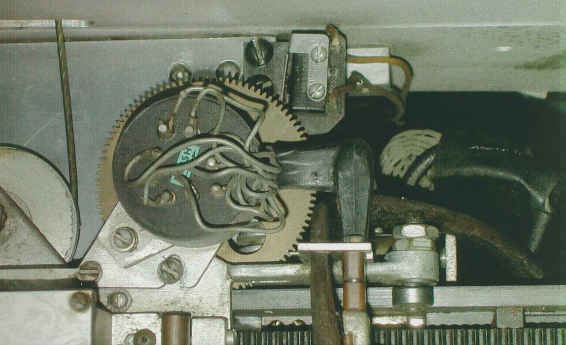
"Our" pot, picture here, has the "random" wiring (coming out of the back of the circular pot in the center)
encased in a rubberoid "potting" compound - making physical access to the connections very
risky and difficult (we all think)
Hitachi Data Systems (which bought IBM's disk business) has a 350 RAMAC with a track pot - all above questions apply.
Dick Oswald would like the track pot question settled before he finalizes his switched ground servo design.
----------------- off line ----------------
I (Ed Thelen) think we should adopt a common vocabulary -
Ed's view of the RAMAC Servo world. (Ed is not a servo guy. Fifty years ago, he did fine in Servo 101,
but did not take the follow-on course, deciding that digital computers were easier and "hot".)
These are preliminary notes of the RAMAC
Tuesday November 14th meeting -
Off-line,
common vocabulary,
Human Interface
A point of reference, this is the "Almadin" track pot as photographed by Dave Bennet.
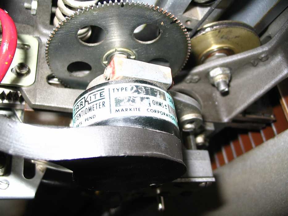
| "Name" | Comment
| Analog Servo
| To me, analog servo is what they teach in
Servo 1 or maybe Servo 101 -
and includes the system used in the 350 !!
| Anything can set up the set point - target, including the 305 setting up the relay trees to set ground at a point of a pot. Other alternatives to setting up a target (set point) can be manual (decimal ;-) switches) and a Digital to Analog converter similar to that used by the students. Nation Instrument's LabView can also be used to set target (set point) and sense and control the various contacts and digital outputs to operate air valves etc. LabView provides an easy development environment, nice GUI (Graphical User Interface), and coded to handle the RAMAC logic and I/O to/from the RAMAC can do a complete loop in about 50 milliseconds. I think the convenient LabVIEW will slow a worst case seek from say 800 milliseconds to maybe 1000 milliseconds - barely noticeable by a human. IBM 305 Implementation | or Switched Null or ... A variant of analog servo (above) using relay trees or equivalent to cause
a zero voltage to appear at the potentiometer
(slider) spot at the disk or track to enable
accurate (low detent wear) insertion to define
the exact disk or track.
| It was noted that the relay tree, with wire contacts, was a significant RAMAC failure source. The servo amplifier drives to cause an input of zero volts, a tachometer is used for velocity feedback. Digital Servo
| a digital machine (the students used a PIC)
can read the target voltage and slider voltage
and the tachometer voltage
(or a summing junction)
and cause the output of driving voltages
(or wave forms in the case of the students)
| A much faster computer can do a very competent job to gain very high performance, using many sorts of optimizations, as in modern disk drives. |
Human Interface
Please Note: The above logic and interface unit do *NOT* handle sector select nor reading and writing. The
data rates and timing requirements for reading and writing are far above the capabilities of the above example and interface unit.
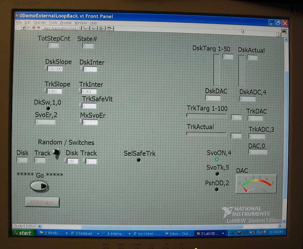
To the left is the "Front Panel" which is set up for linear disk and track pots. You may notice the user adjustable
slope and offset values for the two pots. The present disk and track positions are shown. A user selectable
disk and track *or* random desired disk and track are also shown - along with the switch to select between
user or random modes
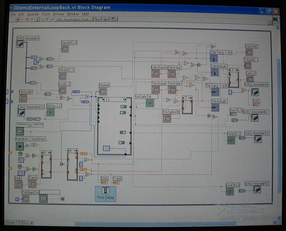
To the left is the control input logic, user interface logic, mode logic, and output logic.
The mode logic is in the large box in the left center. Each of the 12 modes or states is another set of wirings
in this box.