Go To Table of Contents
|
BRL 1961, CCC REAL TIME, start page 0194
|
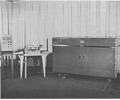
CCC REAL TIME
General Purpose Real Time Tracking Computer
MANUFACTURER
Computer Control Company, Incorporated
Photo, 50 K bytes
Photo by Computer Control Company, Incorporated
APPLICATIONS
The system was specifically designed for use in pro-
viding real-time command signals to position two
85' parabolic antennas from various input sources.
The computations involve parallel correction, orbital
integration, coordinate translation, rotation and
conversion. The computation must be slaved to real
time and solution time must be extremely fast to re-
duce system real time phase shift. Flexibility and
future system requirements are provided by the gen-
eral purpose stored program philosophy.
PROGRAMMING AND NUMERICAL SYSTEM
Internal number system Binary
Binary digits/word 25
Binary digits/instruction 25
Instructions per word 1
Instructions decoded 48
Arithmetic system Fixed point
Instruction type One plus one
Instruction contains one operand address and next
instruction address
Number range +- 1
|
BRL 1961, CCC REAL TIME, start page 0195
|
Instruction word format
Operation Code Address 1 Address 2 Index Control
Automatic built-in subroutines include sine/cosine
resolver, octant reduction, and Binary Coded DecimalBinary
conversion.
There are 3 index registers which may be incremented,
replaced or cleared and are capable of modifying either
address under control of two index control bits located in
each instruction.
ARITHMETIC UNIT
Operation Incl Stor Access Exclud Stor Access
Microsec Microsec
Add 25 25
Milt 75 50
Construction (Arithmetic unit only)
Transistors 540
Arithmetic mode Serial-parallel
Additions are performed in serial, multiplication is
performed in serial-parallel to achieve 50 microsec
multiply time.
Timing Synchronous
Operation Sequential
STORAGE
No. of No. of Access
Media Words Digits Microsec
Acoustic Delay Line 320 8,000 500 Avg.
(Instruction Storage)
Acoustic Delay Line 160 4,000 250 Avg.
(Data Storag )e
Electromagnetic 8 200 25
Delay Line
INPUT
Media Speed
Paper Tape 60 octal digits/sec
Program input tape and position command tape
Antenna Readout 4,000 18 bit words/sec
4 registers containing antenna positions of azimuth
elevation, hour angle, and declination
Theodolite 1,000 readings/sec
Keyboard
The read time from central range timing system is also
made available to the computer for programming
utilization.
|
BRL 1961, CCC REAL TIME, start page 0196
|
OUTPUT
Media Speed
Readout to Digital. Servo 1 reading/sec Computer output
drives 4 command registers, two for each antenna.
Printer 4 words/sec
CIRCUIT ELEMENTS OF ENTIRE SYSTEM
Type Quantity
Diodes 22,000
Transistors 2,700
POWER, SPACED WEIGHT, AND SITE PREPARATION
Power, computer 0.4 Kw
Volume, computer & 105 cu ft
digital servos
Area, computer & servos 15 sq ft
Floor loading 150 lbs/sq ft
150 lbs concen max
Weight, computer 2,200 lbs
|
BRL 1961, CCC REAL TIME, start page 0197
|
PRODUCTION RECORD
Number produced to date 1
Number in current operation 1
Time required for delivery 6 months
COST, PRICE AND RENTAL RATES
The cost of the entire system, including 2 digital servo
racks and all development, installation and programs is
$330,000.
PERSONNEL REQUIREMENTS
One 8-Hour Shift
Operators 1
Engineers 1
Training made available by the manufacturer to user
includes operation and maintenance. The programs having
once been prepared are utilized without need of further
programming unless the computer is to be used for new and
different modes of operation. Since the existing programs
meet the present system needs, no current programming
effort is utilized.
RELIABILITY, OPERATING EXPERIENCE,
AND TIME AVAILABILITY
System features and construction techniques utilized by
manufacturer to insure required reliability includes
completely transistorized and modularized construction.
Package types are limited to 8. 98% of the systems utilize
4 package types.
ADDITIONAL FEATURES AND REMARKS
The arithmetic unit is designed to perform fast computation
of trigonometric functions. The quantity a + bx + c may be
formed in 50 microsec. The system operates in real time and
is synchronized to external range timing system.
--------------------
|
BRL 1961, CDC 160, start page 0198
|
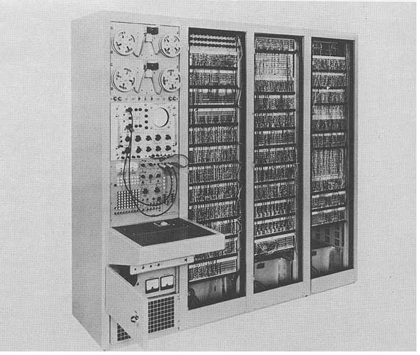
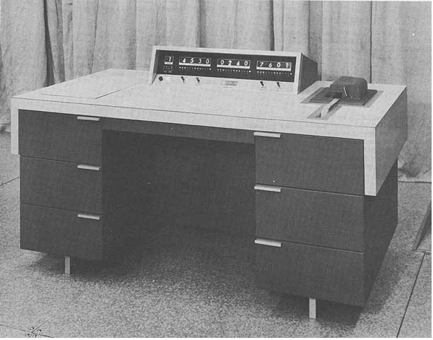
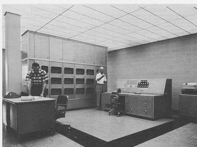
CDC 160
Control Data Corporation Model 160
MANUFACTURER
Control Data Corporation
Photo, 50 K bytes
Photo by Control Data Corporation
APPLICATIONS
The fields of application include off-line data
conversion, data processing - scientific, data processing -
commercial, construction, machine tool design, optical
design, data acquisition and data reduction, and as a
satellite system with the CDC 1604 Computer.
PROGRAMMING AND NUMERICAL SYSTEM
Internal number system Binary
Binary digits/word 12
Binary digits instruction 12
Instructions/word 1
Instructions decoded 63
Arithmetic system Fixed point Mod 212 - 1
Instruction type One address
Flexible addressing modes include no address, direct
address, indirect address, and relative address. Information
in registers shown on projection display
in Arabic numerals.
Instruction word format
+----------------+----------------+
| Function | Address |
+----------------+----------------+
| 6 bits | 6 bits |
+----------------+----------------+
ARITHMETIC UNIT
Operation Incl Stor Access Exclud Stor Access
Microsec Microsec
Add 6.4, 12.8, 19.2 6.4
Mult Programed 1,000
Div Programmed 1,800
Construction (Arithmetic unit only)
Transistors and Diodes
Arithmetic mode Parallel
Timing Asynchronous
Operation Sequential
|
BRL 1961, CDC 160, start page 0199
|
Architecture, 34 K bytes
Diagram by Control Data Corporation
STORAGE
No. of No. of Access
Medium Words Digits Microsec
Core Storage 4,096 49 and 52 bits 6.4
Magnetic Tape
No. of units that can be connected 30 Units
No. of chars/linear inch of tape 200 Chars/inch
Channels or tracks on the tape 7 Tracks/tape
Blank tape separating each record 0.75 Inches
Tape speed 75 or 150 Inches/sec
Transfer rate 15,000 or 30,000 Chars/sec
Start time 5 Millisec
Stop time 5 Millisec
Average time for experienced 45 Seconds
operator to change reel of tape
Physical properties of tape
Width 1/2 Inches
Length of reel 3,600 Feet
Composition Mylar
INPUT
Media Speed
Paper Tape (Ferranti) 350 char/sec
Typewriter
OUTPUT
Media Speed
Teletype Punch 60 char/sec
Typewriter 10 char/sec
CIRCUIT ELEMENTS OF ENTIRE SYSTEM
Type Quantity
Diodes 7,000
Transistors 1,400
Magnetic Cores 49,152
POWER, SPACE, WEIGHT, AND SITE PREPARATION
Power, computer only 0.7 Kw 1.0 pf
Volume, computer 20 cu ft
Area, computer 10 sq ft
Floor loading 700 lbs concen max
Room size is dependent on peripheral equipment se-
lected.
Weight, computer 700 lbs
Air conditioner is dependent on room size and periph-
eral equipment. System uses 110v, 60 cycle power.
PRODUCTION RECORD
Number produced to date 7
Number in current operation 4
Number in current production 25
Anticipated production rates 1 per week
Time required for delivery 6 months
COST, PRICE AND RENTAL RATES
Purchase Lease Price
Price Month
160 Computer $60,000 $1,500
Electric Typewriter 10,500 262
1609 Card Read & Punch Unit 47,000 1,175
Basic Magnetic Tape Unit 37,000 925
(30 KC)
Additional Magnetic Tape 20,500(ea) 512 (ea)
Units (30 KC)
Basic Magnetic Tape Unit 32,000 800
(15 KC)
Additional Magnetic Tape 15,500(ea) 390 (ea)
Units (15 KC)
1606 High Speed Printer 110,000 3,300
A11 prices are f.o.b. Minneapolis, Minnesota, and do not
include Federal, State and Local Taxes which may be
applicable. Subject to change without notice.
PERSONNEL REQUIREMENTS
One 8-Hour Shift
Programmers 2
Technicians 1
Training made available by the manufacturer to users
includes regularly scheduled training courses are made
available to customer personnel. Cost of training is
included in the equipment price.
RELIABILITY, OPERATING EXPERIENCE,
AND TIME AVAILABILITY
System features and construction techniques utilized by
manufacturer to insure required reliability includes solid
state unitized construction and wide tolerances designed
into all circuits.
ADDITIONAL FEATURES AND REMARKS
Outstanding features include high speed input-output,
flexible address features, low cost, and magnetic core
memory:
Unique system advantages include satellite operation with
Control Data Corporation 1604 Computer, small size, and high
speed.
|
BRL 1961, CDC 160, start page 0200
|
160 PERIPHERAL EQUIPMENT
Electric Typewriter
This is an IBM electric typewriter modified by Soroban
Corporation. It has a standard keyboard. The typewriter is
mounted on a cabinet with the controls and power supply
inside the cabinet -connected to the 160 by the input-
output cable. It accepts input data at normal typing
speeds. It prints output data from the 160 at a rate of 10
to 12 characters per second. Associated with the typewriter
is a control panel. It houses two switches and two lights.
The switches denote Operation Mode and Input Disconnect.
1609 Card Read and Punch Unit
This is an IBM 521 punching unit. It provides the 160
with punched card input put and output. There are three
card stations: first reading station, punching station,
second reading station. Calculated results are punched at
the punching station. At the second reading station, a card
can be read for gang punching, re-calculation for proof,
and double punch, blank column checking. Cards are fed
continuously without interruption for calculation. As the
results are being punched in one card, factors are being
read from the following card. May be operated as an
independent gang punch. It operates at a speed of 100 cards
per minute. Two double section, 22-hub control panels and
standard complements of self-contacting wires are
furnished.
Basic Magnetic Tape Unit
It contains controls for a total of four tape handlers.
Uses Ampex FR-300 tape handler, with a character rate of 30
KC. "Change-on-ones" type of recording is used compatible
with that used by IBM 727 tape units. Reflective spots
indicate beginning and end of tape. Thus, a reel of tape
generated by the tape unit can be used on an IBM 727 tape
unit and vice versa. Forward, reverse, and rewind tape
speed is 150 inches per second. Recording density is 200
characters per inch, with 6 information bits and one parity
bit per character. Tape width is 1/2 inch. Data is recorded
in variable-length blocks, with practical limits determined
by the size of memory. Length of inter-block spacing is
approximately one inch. Data transmissions to and from the
tape system are in the form of 6-bit words. Tape can be
read in either the forward or backward direction. For
writing, the control section receives a 6-bit word and
generates a parity bit for each word. Reading follows the
reverse procedure: 7-bit characters are read off the tape
and the lower 6 bits are transmitted to the computer.
Parity checks are made on reading and writing by a read-
head mounted 0.4 inches following the write head. Parity
errors are registered on a flip-flop for subsequent sensing
by the computer. A parity error does not immediately halt
operations, unless a program stop is specified. The reading
and recording heads are electrically isolated on this tape
unit. This feature allows the tape to be read back during
recording for a positive check on both the recording
circuits and the magnetic tape quality. Same unit is
available using FR-400 tape handler, with a character rate
of 15 KC. Additional magnetic tape units are available.
1606 High Speed Printer
The Line Printer consists of an Anelex series 56160
printer and the necessary control circuitry. This printer
provides high speed printing at a normal rate of 350 lines
per minute. It will handle forms from 4 to 20 inches wide
and any length up to 22 inches. It provides 120 columns of
characters and 47 characters per column. These may be
digital, digital and signs, or full alpha-numeric; also
foreign language and plotting symbols. It will print on
single or multiple carbons, pressure sensitive or heat
transfer type papers, pre-printed forms or card stock.
Additional Description - General
Operation of the 160 is sequenced by an internally stored
program. This program, as well as the data being processed,
is contained in the high-speed, random-access memory. An
instruction is a 12-bit word consisting of: a 6-bit function
code F, and a 6-bit execution address E. By means of the
direct, relative, and indirect addressing features, it is
very simple to operate on data in the computer and to make
program modifications when desired.
A general purpose input channel and output channel are
provided for attaching a variety of input-output devices to
the 160 Computer. Standard inputoutput equipment consists of
a Ferranti punched paper tape reader that reads 350
characters per second; and the Teletype high-speed paper
tape punch that operates at 60 characters per second.
Optional input-output equipment includes an on-line electric
typewriter, up to 8 magnetic tape handlers (Ampex FR-300
handlers that operate at 30 KC character rate or Ampex FR-
400 handlers that operate at 15 KC character rate), card
reader-punch units, and line printer. Input-output
transmissions are either a single 6-bit or 7-bit character,
or a 12-bit word.
Description of Registers
The 160 Computer contains three operational registers: A,
Z, and P. The contents of these re isters are shown in
arabic numerals (octal notation on the control panel of the
computer. There are also three transient registers: B, F,
and S. These registers are described below; a block diagram
of the 160 Computer is shown in the figure.
A Register (12 bits): principal arithmetic register. For
most arithmetic operations, A operates as a 12-bit
subtractive accumulator. The quantity zero is represented b
all zeros.
Z Register (12 bits: performs several functions. One, it
serves as a buffer register for storage. In this capacity,
it receives the word read out of storage and holds the word
to be written into storage. Also, for addition and
subtraction operations, the contents of the Z register are
added to or subtracted from the contents of A.
P Register (12 bits): program control register. Its
contents are the address of the current instruction. At the
beginning of each instruction, the contents of P are
increased by one to provide the address of the instruction;
a jump address is entered in P if a jump is called for.
|
BRL 1961, CDC 160, start page 0201
|
B Register (12 bits): auxiliary arithmetic register. The
results of arithmetic operations are first formed in B,
then transmitted to the A, Z, or S registers.
S Register (12 bits): functions as the storage address
register. Prior to any storage reference, the address
word is entered in S. The contents of S are then used to
select the storage location involved in the reference.
F Register (6 bits): holds the upper six bits of an
instruction word, i.e., the function code, throughout
the execution of an instruction. The execution of an
instruction is under the control of the quantity in F.
Addressing Modes
In the direct addressing mode, the address refers to a
12-bit operand in one of the first 64 storage locations.
Indirect addressing provides for operand references
and ,jump addresses. Where indirect addressing is used
with an instruction, E refers to one of the first 64
storage locations; the contents of this register are
then read out and used as the address of the operand or
as the jump address.
Relative addressing provides for operand addresses and
jump addresses that are in the immediate vicinity of the
storage location which contains the current instruction. In
relative addressing forward, the E portion is added to the
current contents of the program control register P. Thus,
the operand or jump address is one of the 63 storage
locations immediately preceding the address of the current
instruction. An exception is the Indirect Jump, in which
the jump address is read from the address found when the
contents of P are added to E.
In the no address mode, constants are stored in the
address portion of the instruction. The E portion of the
instruction is not used as an address. Instead, it is used
as a 6-bit operand. This operand is automatically extended
to 12 bits, with the upper six bits being zeros. With this
feature, arithmetic and logical operations can be carried
out with a 6-bit quantity contained in the instruction.
Thus the need for entering many constants into memory is
eliminated.
|
BRL 1961, CDC 1604, start page 0202
|
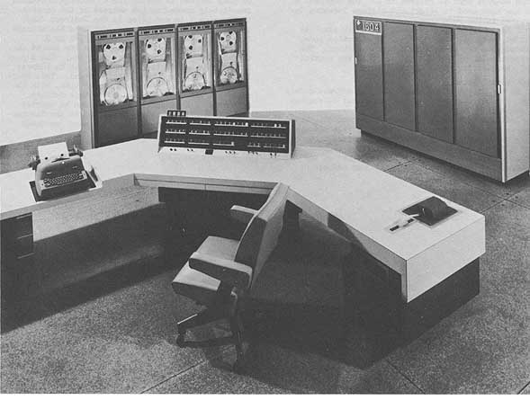
CDC 1604
Control Data Corporation Model 1604
MANUFACTURER
Control Data Corporation
Photo, 50 K bytes
Photo by Control Data Corporation
APPLICATIONS
Manufacturer Actual applications include
engineering, scientific, business, radar, missile tracking,
and educational. U. S. Naval Postgraduate School Located at
Monterey, California, the system is used for scientific
applications, including student and faculty research in
practically all phases of the physical sciences; for data
processing, including weather prediction, and for
simulation, including electronics systems, and games
(business, industrial and military).
National Bureau of Standards - Boulder, Colo. Located at
Boulder, Colorado, the system is used for scientific
computing on Radio Propagation, Radio Standards, and
Cryogenics Research.
PROGRAMMING AND NUMERICAL SYSTEM
Manufacturer
Internal number system Binary
Binary digits/word 48
Binary digits/instruction 24
Instructions per word 2
Instructions decoded 62
Arithmetic system Floating point
one's complement
Fixed point
one's complement
Instruction type One address
Number rangeFixed point +- (247 - 1)
Floating point 10 bit exponent plus
sign, 36 bit coefficient plus sign
|
BRL 1961, CDC 1604, start page 0203
|
Instruction word format
+--------------+-----------+-----------------------+
| 6 bits | 3 | 15 |
+--------------+-----------+-----------------------+
| Instruction | Index | Execution Address |
| Code | Design. | |
+--------------+-----------+-----------------------+
Indirect addressing built in.
Registers include 6 index registers of 15 bits each and a
Ones-complement arithmetic register.
A-Register (Operational) Principal arithmetic register.
Functions as a 48-bit accumulator in most arithmetic
operations. Quantity zero represented by a binary zero in
each stage. Contents of A may be shifted either to the right
or left. Shifting may involve only the contents of A or may
include the contents of Q. Leftmost sign bit extended on
shifts to right; bits shifted off the right end of A or Q
are dropped. Left shifts are circular, with lower order bits
being replaced by higher order bits. Multiply, divide, and
floating point instructions are sequenced operations
involving both A and Q.
Q-Register (Operational) Assists accumulator in
performing more complicated arithmetic operations. Used
with A to perform double precision arithmetic.
Q may be shifted right or left, singly or in conjunction with
A. Q also contains mask in logical operation.
Program Control Register, U1 Holds program step while the
two instructions contained in it are executed. The 48-bit
instruction word taken from storage location specified by P
and entered in U1, the upper instruction being executed first.
Execution of lower instruction follows, except when upper
instruction is a ,jump or when it provides for conditional
skipping of lower instruction.
Auxiliary Program Control Register, U2 An accumulator
used in the modification of execution address of current
instruction. This modification consists of adding contents
of an Index Register to execution address of current
instruction.
P-Register (Operational) Functions as the program address
counter. Provides continuity between individual steps of
program by generating the addresses at which individual
steps are contained. Upon completion of each sequential
step, count in P is advanced by one to specify address of
next step. Jump instructions clear P and enter new address
in it.
|
BRL 1961, CDC 1604, start page 0204
|
site layout, 106 K bytes
Index Registers, B1-B6 (Operational) Provide
modification of execution addresses in program loops. Contents
of an Index Register can be advanced each pass through a
loop, with an exit initiated on a given threshold. Alternate
approach allows an Index Register to be preset, then reduced
by one count each pass through the program-with an exit
after zero.
Storage Address Registers, S1-S2 Represent even and odd
16,384-word memory units respectively. Receive addresses of
instructions from P and addresses of operands from U2.
Storage Restoration Registers, Z1-Z2 Represent even and
odd 16,384-word memory units respectively. Hold the 48-bit
word to be written in a given storage location.
R-Register Functions as exchange register for transmission
involving B-Index Registers. Used in advancing or reducing
count in a given B-Register. During several instructions,
used to count repetitive operations. R used with floating
point instructions in performing arithmetic operations on
the exponent or characteristic.
X-Register An exchange and auxiliary arithmetic
register. All input-output data passes through X.
External Function Register, 00 Used for exchanging
control information with input-output equipment.
Output Registers, 01 through 04 01 through 03 used for
output buffer operations where data is transmitted at speed
of input-output equipment. Where high-speed transfer is
required, output transfer operations carried out via 04.
ARITHMETIC UNIT
Incl Stor Access
Microsec
Add 4.8 - 9.6
Mult 25.2 + .8N
Div 63.6 - 66.4
N = Number of ones in multiplier
Arithmetic mode Parallel
Timing Synchronous
Operation Concurrent
STORAGE
Manufacturer
No. of No. of
Media Words Digits
Magnetic Core 32,768 48
Magnetic Tape
No. of units that can be connected 24 Units
No. of characters/linear inch 200 Chars/inch
Channels or tracks on the tape 7 Tracks/tape
Blank tape separating each record 3/4 Inches
Tape speed 150 Inches/sec
Transfer rate 30 K Chars/sec
Stop time 1.2 Millisec
Average time for, experienced
operator to change reel of tape 20 Seconds
Physical properties of tape
Width 1/2 Inches
Length of reel 2,500 Feet
24 tape stations is a practical maximum, although
more may be used.
U.S. Naval Postgraduate School
No. of No. of Access
MediumWords Dig Word Microsec
Magnetic Core 32,768 48approx. 4.8
National Bureau of Standards - Boulder, Colo.
Magnetic Core 32,768 48 4.8 (effective)
INPUT
Manufacturer
Media Speed
Paper Tape 350 char/sec
Typewriter
Punched Cards 150 cards/min
Magnetic Tape 30,000 char/sec
Faster punched card units will be available soon.
U. S. Naval Postgraduate School
Paper and Magnetic Tapes
|
BRL 1961, CDC 1604, start page 0205
|
National Bureau of Standards - Boulder, Colo.
Media Speed
IBM 088 Collator 650 cards/min
Two read feeds are available.
Paper Tape (Ferranti)350 char/sec
OUTPUT
Manufacturer
Media Speed
Paper Tape 60 char/sec
Typewriter
Punched Cards 100 cards/min
Magnetic Tape 30,000 char/sec
Line Printer 667/1,000 lines/min
U.S. Naval Postgraduate School
Paper Tape 60 char/sec
Magnetic Tape 150 in/sec 200 char/in
Monitoring Typewriter
IBM 717 Printer 150 lines/min 120 char/line
Off line Mag tape to printer
National Bureau of Standards - Boulder, Colo.
IBM 523 Punch 100 cards/min
IBM 407 Printer 150 lines/min
Magnetic Tape
CIRCUIT ELEMENTS OF ENTIRE SYSTEM
Manufacturer
Type Quantity
Diodes 100,000
Transistors 25,000
Magnetic Cores 1,500,000
POWER, SPACE, WEIGHT, AND SITE PREPARATION
Manufacturer
Power, computer 7.5 Kw
volume, 1604 Computer 98 cu ft
Volume, 1604 Console 112 cu ft
Area, computer 17 sq ft
Area, console 30 sq ft
Floor loading 150 lbs/sq ft
2,650 lbs/concen max
Capacity, air conditioner 5 Tons
Weight, computer and
console 5,450 lbs
Weight, air conditioner 500 lbs
Power, space and weight figures are for 1604. Computer and
console peripheral equipment is not included. The alternator
is driven by a 15 HP motor.
U. S. Naval Postgraduate School
Power, computer 4 Kw
Room size 2,800 sq ft
Floor loading 200 lbs/sq ft
700 lbs concen max
Capacity, air conditioner 25 Tons
Weight, computer 2,200 lbs
The lobby section of one of the school buildings was
partitioned. False flooring, air conditioning and power
were installed in the laboratory section which houses two
computers (CDC-1604 & NCR-102A) and their associated
peripheral equipment.
National Bureau of Standards - Boulder, Colo.
Power, computer 15 Kw
Room size 24 ft x 24 ft
Capacity, air conditioner 6 Tons
System is installed on a raised floor in a specially
prepared computer room.
PRODUCTION RECORD
Manufacturer
Number produced to date 6
Number in current operation 6
Number in current production 10
Number on order 6
Anticipated production rates 1 per month
Time required for delivery 9 months
COST, PRICE AND RENTAL RATES
Manufacturer
Lease Price/Month
Purchase 1 Year 3 Year
Price Contract Contract
Basic computer, with $750,000 $22,500 $18,750
8,192 words Mag Core Stor
16,384 words Mag Core
Stor 830,000 25,000 20,750
32,768words Mag Core
Stor 990,000 30,100 24,750
Above computer includes:
Magnetic Core Storage:
Two phase system with
3.2 microseconds effective cycle time, alternate banks
6.4 microseconds cycle time, each bank
Fixed Point Arithmetic
Floating Point Arithmetic Feature
Indirect addressing
Control and Maintenance Conscle
Motor-generator
Input Punched Paper Tape Reader (7 channels, 350
characters per second)
Output Punched Paper Tape Punch (7 channels, 60
characters per second)
Input/Output Modified IBM Typewriter
(directconnected)
Installation and checkout at customer premises
Site preparation not included
Maintenance and instruction books
Model 1607 Magnetic $145,000 $5,050 $3,625
Tape Subsystem
Includes Magnetic Tape Synchronizer
Four magnetic tape handlers
30 KC character rate
6 information bits, 1 parity bit per character
Parity-bit check on read and write
48-bitassembly for central computer
IBM 727 Format
Note:Up to 6 Magnetic Tape Subsystems can be used
with each Model 1604.
Model 1605 Adaptor $70,000 $2,050 $1,750
Permits direct communication between Model 1604
and following IBM input/output equipment
IBM 714 card reader (via 759 control unit)
IBM 727 magnetic tar units (via 754 synchronizer)
IBM 722 card punch ia 758 control unit)
IBM 717 line printer (via 757 control unit)
Transistor Chassis Tester $9,000
(non-automatic)
|
BRL 1961, CDC 1604, start page 0206
|
Lease Price/Month
Purchase 1 Year 3 Year
Price Contract Contract
Modifications Added after
Model 1604 Construction or
Delivery:
Magnetic Core Storage:
Add 8,192 words to 1604
with 8,192 words $100,000
Add 16,384 words to 1604
with 16,384 words 200,000
Add Model 1607 Magnetic
Tape Subsystem (each) 150,000
Model 1606 High Speed
Printer 110,000 3,300 3,300
Operates at a rate
of 1,000 lines per
minute with the 1604.
All prices are f.o.b. Minneapolis, Minnesota, and do not
include Federal, State, and Local Taxes which may be
applicable. Prices are subject to change without notice.
U.S. Naval Postgraduate School Computer, with 4 tape
drives, console, photo electric reader and teletype punch
is approx. $800,000. IBM 717, 727 and 757 rent at approx.
$2300 per month. Maintenance/service contract with Control
Data Corporation amounts to $17,500/year.
National Bureau of Standards - Boulder, Colo. Rates
for basic system is $36,660 per month. Rental rate for
IBM Input-Output equipment is $1,340/month.
PERSONNEL REQUIREMENTS
Manufacturer
one 8-Hour Two 8-Hour Three 8-Hour
Shift Shifts Shifts
Engineers 1 2 2
Technicians 1 1 2
Training made available by the manufacturer to the user
includes regularly scheduled training courses, furnished
for customer personnel at our plant in Minneapolis,
Minnesota. These courses are included in the equipment
price.
U.S. Naval Postgraduate School
One 8-Hour Shift
Used Recommended
Supervisors 1
Programmers 1 3
Clerks 1 3
Operators 2
Engineers 1 2
Technicians 1 2
Operation tends toward open shop.
Methods of training includes course work given in the
Engineer School on programming, operation and applications
and also seminars are given at the school.
The computers are available for student and faculty research
24 hours per day. Those students and faculty who have been
checked-out on the operation of the computers and peripheral
equipment are permitted out-of-hours production runs on the
computers. Potentially the school has approximately 1000
programmeroperators under this system. At the present time the
CDC1604 operates approximately 14 hours per day
andthe NCR 102A 20 hours per day, 7 days per week.
National Bureau of Standards - Boulder, Colo.
One 8-Hour Shift
Supervisors 1
Analysts 3
Programmers 3
Operators 2
Methods of training used include programing train. ing
courses using CDC manuals.
RELIABILITY, OPERATING EXPERIENCE,
AND TIME AVAILABILITY
Manufacturer
System features and construction techniques utilized by
manufacturer to insure required reliability include solid
state components throughout and wide tolerances designed
into all circuits. U.S. Naval Postgraduate School Passed
Customer Acceptance Test 16 Jan 60 Time is not available
for rent to outside organizations.
ADDITIONAL FEATURES AND REMARKS
Manufacturer
Outstanding features include 48 bit word length, 6
buffer input-output channels, program interrupt feature,
six index registers, and floating point arithmetic.
Unique system advantages include high speed transfer
channel, and satellite operation with 160 computer.
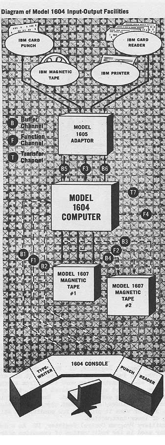
Summary of Buffer Operation
The Model 1604 buffer control continually interrogates
all communication channels to determine if a peripheral
equipment is ready to send or receive information.
If a peripheral equipment has data ready for transfer,
interrogation waits momentarily while a word is being
buffered. The buffer control then resumes interrogating the
communication channels.
Buffering initiates communication between computer
memory, the three buffer input channels, and the three
buffer output channels. These buffer information in and out
asynchronously with the main computer program.
The three buffer input channels and the three buffered
output channels, the interrupt line, and the real-time clock
are rapidly scanned by a scanner which looks for action
requests from all channels. These action requests are
initiated by the peripheral equipment by indicator "flags".
A complete scan is made in 3.2 microseconds, which
corresponds to the phase rate of magnetic core memory.
When a request is detected by the scanner, the main
computer program is halted momentarily to move the data
between memory and the requesting channel. The main
program proceeds immediately after this action unless the
scanner detects that another channel has requested
servicing. For example, if the system includes six 1607
magnetic tape systems, all three buffered input channels
and all three buffered output channels of the 1604 can
operate in the buffer mode, simultaneously servicing at
full tape-rate three 1607 magnetic tape units operating in
the read mode and three 1607 magnetic tape units operating
in the write mode.
|
BRL 1961, CDC 1604, start page 0207
|
Summary of High Speed Transfer Operation
The main computer program performs the high-speed input-
output transfer of information between 1604 's or between
one 1604 and peripheral equipment having comparable speed.
Only one instruction is required for a block of input or
output data. A 48-bit word is transferred in or out in 4.8
microseconds.
All transfer operations are carried out via channel 7.
Summary of Program Interrupt
The Model 1604 recognizes an interrupt signal which may
be either a signal indicating that a peripheral equipment
has completed sending or receiving information or it may
be a fault condition, e.g., an overflow.
A subroutine determines what has caused the interrupt,
e.g., what specific peripheral equipment is causing the
interrupt and on which channel the interrupt is taking
place.
The subroutine takes action with the originating
peripheral equipment by first removing the interrupt
signal to prevent re-recognition.
The appropriate condition is set up in compliance with the
interrupt. If it has come from a peripheral equipment, the
action is completed-after which there is a return to the
main computer program.
Summary of External Function
This instruction provides control and communication
between the Model 1604 and peripheral equipment. It
contains eight sub-instructions which select and sense
peripheral equipments, or activate buffer channels.
The select sub-instruction (74.0) is interpreted as
follows: the leftmost 6 bits are the operation code, the
next 3 bits designate that this is a select sub-
instruction, the next 3 bits are the channel or internal
condition selection code, the next 3 bits are the
equipment selection code, and the last.9 bits specify the
operation for the selected equipment.
The channel activate sub-instructions 74.1 through 74.6
are interpreted as follows: the leftmost 6 bits are the
operation code, the next 3 bits designate that his is an
activate sub-instruction (plus indicating the channel), and
the last 15 bits indicate the initial address for data
storage in the buffer operation.
The sense sub-instruction 74.7 is interpreted as follows:
the leftmost 6 bits are the operation code, the next 3 bits
designate that this is a sense subinstruction, the next 3
bits are the channel or internal condition selection code,
the next 3 bits are the equipment selection code, and the
last 9 bits specify the operation for the selected
equipment.
Model 1607 Magnetic Tape System
A Model 1607 Magnetic Tape System consists of four Ampex
magnetic tape handlers. The system is selfcontained in a
single cabinet, including data-handling and control
circuitry; 48-bit assembly and disassembly registers;
parity bit assignment for each
written character; parity bit read-check immediately
following each character written; longitudinal parity bit
generation and recording at end of block; parity bit
detection for each character read; and end of tape sensing.
Each 1607 tape system can be connected to any of the
three buffer input and three output channels, and each
1607 is independently addressable. A number of 1607's ca
be connected to a 1604 Computer.
Simultaneously among these 1607 tape systems, three tape
handlers can be reading, and three tape handlers can be
writing. Each 1607 system has the facility for simultaneously
reading from one tape handler and writing on one tape
handler, while the remaining two tape handlers are rewinding.
Any tape can read either in a forward or reverse direction.
Magnetic tapes of the 1607 tape system are completely
compatible electrically and mechanically with IBM Model 727
magnetic tape handlers.
Model 1605 Adaptor
The Control Data Model 1605 Adaptor permits communication
between the 1604 Computer and any of the following IBM
peripheral equipment: 714 Card Reader (via 759 Control Unit)
727 Magnetic Tape Units (via 754 Synchronizer) 717 Line
Printer (via 757 Control Unit) 722 Card Punch (via 758
Control Unit)
The 1605 selects one of these peripheral equipments, as
well as the operation to be performed, on the basis of an
instruction from the main computer program. For example, a
buffer instruction initiates the transfer of information
between the 1604 Computer and the selected equipment via the
Model 1605 Adaptor. A parity check is made on all information
transmitted from the 1605 to peripheral equipment.
Each 1605 Adaptor can be connected to any of the three
buffer input and three buffer output channels, and each 1605
is independently addressable. The 1605 has the same 48-bit
input and output buffer register characteristics as the 1607
Magnetic Tape System. A number of 1605's together with a
number of 1607's can be operated with a singe 1604 Computer.
For special applications, Control Data Corporation will
supply special input-output adaptors for peripheral
equipments, such as special display and output systems, radar
and sonar systems, digital communication.systems, and real-
time instrumentation systems.
FUTURE PLANS
U. S. Naval Postgraduate School
Plans include
procurement of the CDC 160 system consisting of the Central
Processor, Card Reader and Punch, Magnetic Tape and
Printer. This system can be connected on-line to the CDC
1604 and used either on or off line.
INSTALLATIONS
U. S. Naval Postgraduate School, Monterey, Calif.
National Bureau of Standards, Boulder, Colo.
U. S. Army Signal Corps, Signal Procurement Office,
Fort George G. Meade, Maryland
U. S. Navy, Bureau of Ships, Washington 25, D. C.
U. S. Naval Air Materiel Center, Aeronautical Structures
Laboratory, Philadelphia 12, Pennsylvania
U. S. Air Force Ballistic Missile Center, Air Materiel
Commend, Los Angeles 45, California
U. S. Air Force 4925 T.G.A. (Area E), Kirtland Air
Force Base, Albuquerque, New Mexico (Proposed)
U. S. Air Force, Vandenberg Air Force Base
U. S. Air Force Structures Test Laboratory, WADC,
Wright Field, Dayton, Ohio
Convair Astronautics, Dayton, Ohio
Lockheed Aircraft Corporation, Missiles Systems
Division, Sunnyvale, California (2)
Institute for Defense Analyses, Weapons Systems Evaluation
Division, Room 1D863, Pentagon, Wash 25, D.(
Institute for Defense Analyses, Upper Payne Bldg., 76 1/2
Nassau Street, Princeton, N. J.
New York University, University Heights, NYC 53, NY
University of California, Institute of Geophysics,
La Jolla, Calif.
|
BRL 1961, Circle, start page 0208
|
CIRCLE
Circle Digital Computer
MANUFACTURER
Hogan Laboratories, Incorporated
Photo, 15 K bytes
Photo by Hogan Laboratories, Incorporated
APPLICATIONS
Manufacturer
General purpose, scientific computation
Engineer Research and Development Laboratories
Scientific and engineering computation
PROGRAMMING AND NUMERICAL SYSTEM
Internal number system Binary
Binary digits per word 40 - 44 plus 2 sign
digits
Binary digits per instruction 20
Instructions not decoded 3
Instructions per word 2
Instructions decoded 64
Instructions used 33
Arithmetic system Fixed point
Instruction typeOne address code
Number range -1 to +1 (1-224)
Shift, Print, Convert Binary to Decimal, and Feed
Instructions make use of Address Digits to determine number
of shifts, digits, etc.
ARITHMETIC UNIT
Exclud Stor Access
Microsec
Add 500
Mult 20,000
Div 20,000
Construction Vacuum tubes
|
BRL 1961, Circle, start page 0209
|
Rapid access word registers Operating Registers
Basic pulse repetition rate 82 Kc/sec
Arithmetic mode Serial
Timing Synchronous
Operation Sequential
Conversion from decimal to binary requires 2,000
microseconds and one instruction.
STORAGE
Medium Words Microsec Access
Drum l,024-4,096 8,000(avg)
42-46 digits per word
INPUT
Media Speed
Paper Tape (Flexowriter) 10 dig/sec
Keyboard (Flexowriter) Manual
Paper Tape (Reader) 30 dig/sec
The paper tape reader is optional.
OUTPUT
Media Speed
Hard Copy (Flexowriter) 10 dig/sec
Paper Tape (Flexowriter) 10 dig/sec
CIRCUIT ELEMENTS OF ENTIRE SYSTEM
Tubes 800-1,000
Tube types 3
Different plug in units 18
Separate cabinets 2
CHECKING FEATURES
Even-odd check on instructions
Programmed check is normally used.
POWER, SPACE, WEIGHT AND SITE PREPARATION
Power, computer 3 - 3.5 Kw
Volume, computer 54-81 cu ft
Weight, computer 1,600 lbs
PRODUCTION RECORD
Number produced 2
Number in current operation 2
This system is no longer being manufactured.
COST, PRICE AND RENTAL RATES
Approximate cost of basic system
$80,000 with 4,096 word storage
$60,000 with 1,024 word storage
Optional features at extra cost were:
Twenty binary digit word operation
Special orders for unusual problems checking
2,048 word storage
PERSONNEL REQUIREMENTS
Daily Operation One 8-Hour Two 8-Hour Three 8-Hour
Shift Shifts Shifts
Engineers 0.5 0.5 0.5
Technicians 1 2 3
RELIABILITY, OPERATING EXPERIENCE,
AND TIME AVAILABILITY
Manufacturer
Good time 813 Hours
Attempted to run time 996 Hours
Operating ratio (Good/Attempted to run time) 0.82
Passed Acceptance Test June 54
INSTALLATIONS
U.S. Army Corps of Engineers
Engineer Research and Development Laboratories
Fort Belvoir, Virginia
Westinghouse Electric Company
Atomic Products Division
Pittsburgh, Pennsylvania
|
BRL 1961, CUBIC AIR TRAFFIC, start page 0205
|
CUBIC AIR TRAFFIC
Cubic Air Traffic
MANUFACTURER
Cubic Corporation
APPLICATIONS
Computer is intended for future air traffic control
applications. The computer now is a specialpurpose unit,
providing 42-target capacity when used with Cubic
Corporation c-w tracking equipment. The computer is a
special-purpose, magnetic memory-drum variety (used with
MOPTAR Cubic multi-aircraft tracking system) which
sequentially determines slant range and two direction
cosines by phase-mearurement techniques to each of 42
separate airborne targets at the rate of 4 samples (each)
per second. Input equipment converts phase information into
a series of binary numbers. The computer successively
performs, for each input sample, (a) special digital
smoothing and filtering operations on each input binary
number, (b) ambiguity resolution between overlapping number
digits to produce a single range and two direction cosine
numbers, (c) computation of aircraft X, Y, and Z position
data and (d) conversion and transmission of computed X, Y,
and Z positions in IBM 704 format over transmission lines.
PROGRAMMING AND NUMERICAL SYSTEM
Internal number system Binary
Binary digits/word 20
Arithmetic system Fixed point
Instruction type Words handled serially
Arithmetic unit effectively programmed to operate on
recirculating data corresponding to particular target
sample being handled.
ARITHMETIC UNIT
Incl. Stor. Access Exclud. Stor. Access
Microsec Microsec
Add 250 250
Mult 250 250
Construction (Arithmetic unit only)
Transistors 750
Arithmetic mode Serial
Timing Synchronous
Operation Sequential
Combination external high-speed multiplier and square-
root extractor employed for multiplication and square
rooting. Additions performed during drum recirculation.
STORAGE
Medium
Magnetic Memory Drum
Digital filtering requires equivalent of 168 words;
ambiguity resolution and coordinate conversion are both
performed in temporary storage corresponding to 5 words in
length. Drum has 12 recirculating channels of approximately
20,500 bits total.
INPUT
Medium
Input equipment includes special phase-to-digital
conversion equipment consisting mainly of flip-flop
counters and clocks. Its overall operation is programmed
by the memory drum.
OUTPUT
Medium
A Cubic standard unit (Model DH-10) places the computed
X, Y, and Z target sample values in IBM 704 format on
output transmission lines.
CIRCUIT ELEMENTS OF ENTIRE SYSTEM
Type Quantity
Diodes 2,000
Transistors 2,600
Computer itself has 750 transistors, input equipment has
1200 transistors, and the DH-10 output unit has 600
transistors.
CHECKING FEATURES
Data sample is not taken if a poor signal is received
form the target. Also, the basic digital filtering
technique is self-correcting in the event of intermittent
arithmetic failures.
PRODUCTION RECORD
Number on order 1
Time required for delivery 12 months
This computer is intended for future air-traffic
control application.
ADDITIONAL FEATURES AND REMARKS
Special-purpose techniques enable this relatively slow,
serial memory-drum computer, with external. high-speed
multiplier, to perform slightly more arithmetic operations
per unit time than can be performed by the IBM 709 class of
general-purpose computers.
|
BRL 1961, CUBIC TRACKER, start page 0210
|
CUBIC TRACKER
Cubic Tracker
MANUFACTURER
Cubic Corporation
APPLICATIONS
All digital computers built by Cubic are Special Purpose
Fixed Program Real Time Computers. Two are in operation at
PMR. Five are scheduled for delivery to WSMR in September,
1960. One in production for HOTS. Prototype developed and
delivered to Eglin A.F.B. Systems are used on line in real-
time.
PROGRAMMING AND NUMERICAL SYSTEM
Internal number system Binary
Binary Digits/word up to 21
Arithmetic system Fixed point
There are several modes of operation, each one containing
its own program. Arithmetic Section contains 21-bit shift
registers plus numerous index registers.
ARITHMETIC UNIT
Incl. Stor. Access Exclud. Stor. Access
Microsec Microsec
Add 20 10
Construction (Arithmetic unit only)
Transistors 100 - 2N597, 100 - T1778
Aritbmetic mode Serial
Timing Synchronous
Operation Sequential
STORAGE
No. of o. of Access
Media Words Digits/word Microsec
Flip-Flops 64 8 - 20 10/bit
Magnetic Tape
No. of units that can be connected 1 Unit
No. of characters/linear inch 200 Chars/inch
Channels or tracks on the tape 7 Tracks/tap Blank tape
separating each .367 - .7045 Inches
record
Tape speed 30- 1.875 Inches/sec
Transfer rate 15 k/s Chars/sec
Width 0.5 Inches
INPUT
Medium Speed
Flip Flop 96 Kc
OUTPUT
Medium Speed
Flip Flop 96 Kc
CIRCUIT ELEMENTS OF ENTIRE SYSTEM
Type Quantity Use
Diodes
PSI720 200 Gating
1N276 450 Gating
1N270 600 Gating
Transistors
2N597 600 Low speed Flip Flop
2N501 600 High speed Flip Flop
T1778 200 Nor Gates
2N385 200 Emitter Follower
CHECKING FEATURES
In the test made of operation all inputs can be
simulated and the clock switched to manual.
POWER, SPACE, WEIGHT, AND SITE PREPARATION
Power, computer 1 Kw
Power, air conditioner 1 Kw
Volume, computer 200 cu ft
Volume, air conditioner 50 cu ft
Area, Computer 40 sq ft
Area, air conditioner 20 sq ft
Room size, computer 20 x 20
Floor loading 50 lbs/sq ft
Capacity, air conditioner 1 Ton
Weight, computer 2,000 lbs
Weight, air conditioner 1,000 lbs
PRODUCTION RECORD
Number produced to date 7
Number in current operation 2
Number in current production 5
Number on order 5
Anticipated production rates 12/year
Time required for delivery 8 - 12 months
COST, PRICE AND RENTAL RATES
List of Components of Basic System
Digital phasemeter Processor Format
translator Tape handler
List of Additional Equipment Co-
ordinate Converter Test unit
Field services are available.
PERSONNEL REQUIREMENTS
System requires one operator for each 8-hour shift. Training
made available by the manufacturer to users includes in
plant and field training.
RELIABILITY, OPERATING EXPERIENCE,
AND TIME AVAILABILITY
All transistors undergo an aging process.
ADDITIONAL FEATURES AND REMARKS
Outstanding features include reliability and simplicity.
FUTURE PLANS
Computers now in production contain automatic calibration.
|
BRL 1961, CYCLONE, start page 0212
|
CYCLONE
CYCLONE
MANUFACTURER
Iowa State University
Photo, 40 K bytes
Photo by Iowa State University
APPLICATIONS
Utilized for general purpose computing to support
research work on campus.
PROGRAMMING AND NUMERICAL SYSTEM
Internal number system Binary
Number of binary digits/word 40
Number of binary digits/instruction 20
Number of instructions/word 2
Total number of instructions decoded 112
To be increased to 152 when modifications are
completed
Arithmetic system Fixed point
(Fractional base)
Instruction type One address
Number range
-(1 - 2-39) <= n < (1 - 2-39)
Instruction word format
+-------+----------+----------+ +--------+------------+------------+
| 4 bit | 4 bit | 12 bit | | 4 bit | 4 bit | 12 bit |
| basic | varient |address | | basic | varient | address |
| op | | | | op | | |
+-------+----------+----------+ +--------+------------+------------+
Automatic built-in subroutines include multiplication.
Automatic coding, assembly program will be completed with
machine modification.
Registers include an accumulator register, a multiplier-
quotient register, an operand register, and an order
register.
|
BRL 1961, CYCLONE, start page 0213
|
ARITHMETIC UNIT
Incl. Stor. Access Exclud. Stor. Access
Microsec. Microsec.
Add 100 av. 70
Mult 990 av. 960
Div 1200 av. 1170
Construction, arithmetic unit only
Vacuum tubes
Type Quantity
5844 1,521
7044 386
5670 431
5726 233
Arithmetic mode Parallel
Timing Asynchronous
Operation Sequential
STORAGE
No. of No. of Access
Medium Words Digits Microsec
Williams tube Electro-static 1,024 40,960 30 av.
INPUT
Medium Speed
Paper Tape - 5 level300 char/sec
Local Design and construction
OUTPUT
Media Speed
Paper Tape -5 level60 char/sec
Model 28 Teleprinter 10 char/sec
CIRCUIT ELEMENTS OF ENTIRE SYSTEM
Type Quantity
Tubes
7044 386
6571 40
813 4
6x4 8
5844 1,521
6080 12
6005 61
5726 233
5654 113
C6J/K 18
CHECKING FEATURES
Fixed
Division error
Optional
CRO on memory read amplifier
Single order execution
Step-wise gating within single order execution
POWER, SPACE, WEIGHT, AND SITE PREPARATION
Power, computer 19 Kw
Volume, computer 400 cu ft
Area, computer 62 sq ft
Room size, computer 18 ft x 25 ft
Floor loading 150 lbs/sq ft
Weight, computer 5,000 lbs
Capacity, air conditioner 6 Tons
PRODUCTION RECORD
Number produced to date 1
Number in current operation 1
Not manufactured for sale.
PERSONNEL REQUIREMENTS
One 8-Hour Two 8-Hour Three 8-Hour
Shift Shifts Shifts
Analysts
Programmers 8 12 16
Coders
Operators 1 2 3
Engineers 1 2 2
Technicians 1 2 2
Training made available to users includes programming
classes conducted on a regular schedule.
Operation tends toward open shop.
RELIABILITY, OPERATING EXPERIENCE,
AND TIME AVAILABILITY
Good time 40.9 hrs/week av.
Attempted to run time 41.2 hrs/week av.
Operating ratio (good time
attempted to run time) 0.992
Above figures based on period 1 May to 30 Jun 60.
System was placed in operation in Jul 59.
Premium components, all connections soldered. Greatest
source of failure is input-output equip
ment. Anticipated error rate is one error in 40 hours
of operation.
ADDITIONAL FEATURES AND REMARKS
The prototype of this machine is ILLIAC, the University of
Illinois Digital Computer. Pertinent information on this
system will be found under this listing.
FUTURE PLANS
Plans for new components include a 64 word output buffer
memory (mag. core) (under construction), a 16,380 word
mag. core memory (under construction to replace 1,024
word Electrostatic Williams tube (CRT) memory, and two
IBM 726 tape units to be coupled into computer (tape
units on hand).
Under consideration are a card reader, a CRT output
camera, and a high speed line printer.
INSTALLATIONS
Iowa State University
Ames, Iowa
Go To Table of Contents