Go To Table of Contents
|
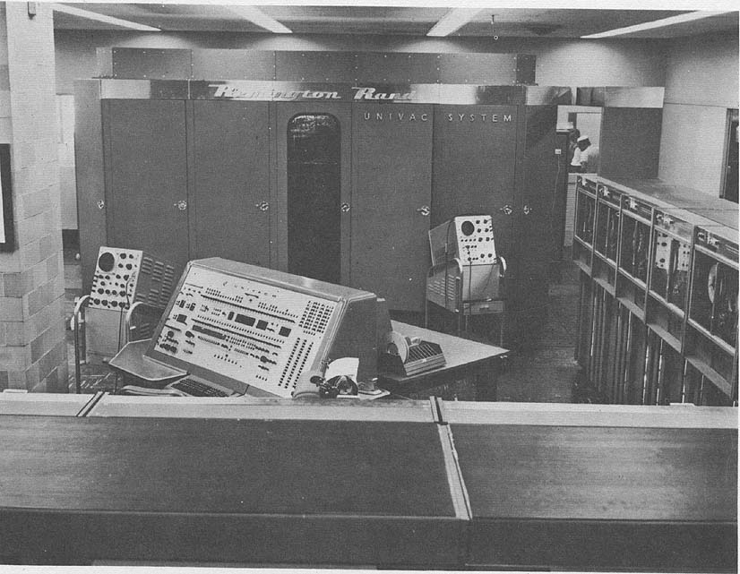
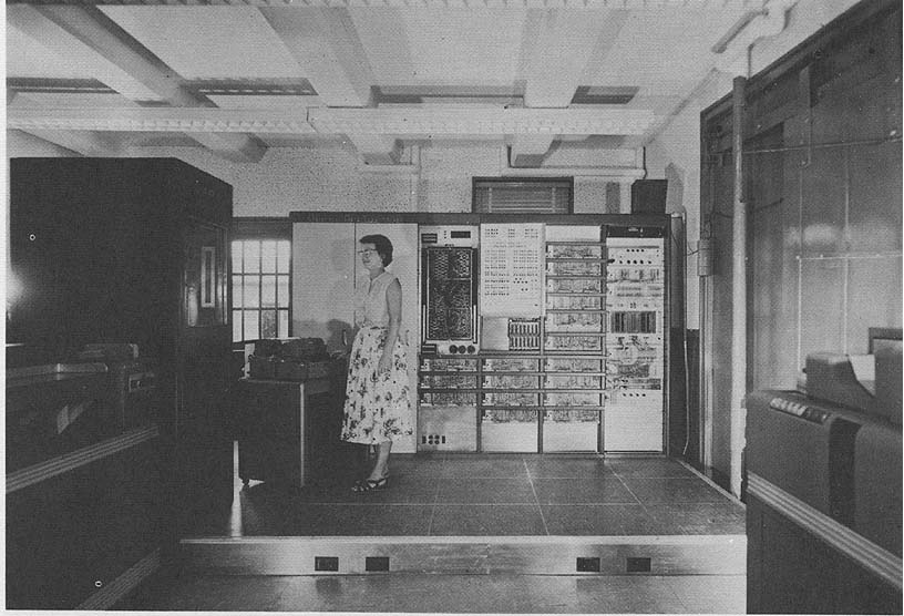
BRL 1961, UNIVAC II, start page 0992
|
UNIVAC II
Universal Automatic Computer Model II
MANUFACTURER
Remington Band Univac Division
Sperry Rand Corporation
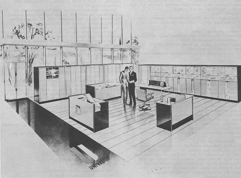
Photo by U. S. Navy Electronics Supply Office
APPLICATIONS
Manufacturer General purpose
digital computer.
U. S. Navy Electronics Supply Office Located at the
Southwest corner of 1st deck, ESO Building, Great Lakes, Illinois,
the system is used for inventory control (180,000 items, 21
stock points $200 million value. Weekly stock review,
redistribution, procurement, and allocation), for electronic repair
parts allowance lists (active plus reserve ships, shore
installations, etc. Weekly process), for stock number
identification (Technical document for use by electronic
technicians), for Tables and Allowance Guides (To maintain and
support a specific model of electronic equipment or system. Tri-
weekly process), for consolidated load lists (Computed and
tailored requirements lists for maintaining proper range and
depth of stock aboard tenders and supply support ships. Semi-
annual process), for stratification of assets and requirements (A
stratified item by-item comparison of system inventory vs future
,needsto identify material which will be purchased
or declared excess during the apportionment and bud-
get fiscal years. Annual processing), for contractor
performance and analysis (Control of material ordered
from suppliers to determine; contractor performance,
cost,procurement lead time and its variation, over-
due contracts, contractor follow-up, etc. Weekly
process) and for management statistics (Various sta-
tistical controls to measure activity and system
effectiveness, stock turn-over, volume of issues,
sales, etc. Weekly and quarterly process).
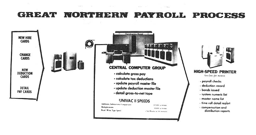
U. S. Department of Agriculture
Commodity Stabilizatlon.Service
Located at the CSS Commodity Office, Kansas City,
Missouri, the system is used in the Grain Price Sup-
port Program. This involves processing price support
loan and purchase agreement transactions for the 31
states served by this office as a data processing
center for this program. This application includes
computation of loan and purchase transactions, prep-
|
BRL 1961, UNIVAC II, start page 0993
|
Photo by U. S. Navy Electronics Supply Office
aration of settlement statements with farmers and producers, and recordation
of accountability for these transactions - approximately 1 million
transactions are processed annually.
Metropolitan Life Insurance Company Located at 1 Madison Avenue,
NYC (3 Univac II's) and 315 Park Avenue So., NYC (across the street - 1
Univac II), the four systems are used for actuarial (classification valuation,
mortality studies and special studies), for debit accounting (preparation of life
and lapse registers), for payroll, for city mortgage accounting, and for ordinary
policy service (billing, dividend calculation, premium, dividend and
commission accounting).
Pacific Mutual Life Insurance Company Located in the Home Office
Building in Los Angeles, California, the computer is used as the integral part of
an integrated data processing system used to do our normal billing, collections,
valuation, lapses, agents records, commissions, loans, claims and just about
every other facet of the ordinary life insurance work. In addition we do some
actuarial studies, agency department contest records and several miscellaneous
jobs.
United States Steel Corporation Located at 150 Muriel Street,
Pittsburgh 3, the system is used for accounting, statistical, analytical,
and engineering (multiple correlations and regression analyses) problems.
PROGRAMMING AND NUMERICAL SYSTEM
Internal number system Binary coded decimal
Decimal digits/word 12
Decimal digits/instruction 6
Instructions per word 2
Instructions decoded 54
Instructions used 54
Arithmetic system Fixed point
Instruction type One address
Number range Between -1 and +1
Decimal point occurs at the right of the sign digit.
ARITHMETIC UNIT
Incl Stor Access Exclud Stor Access
Microsec Microsec
Add 160 120
Mult 1,720 1,680
Div 3,030 2,990
Construction Vacuum tubes
Arithmetic mode Serial
Timing Synchronous
Operation Sequential
|
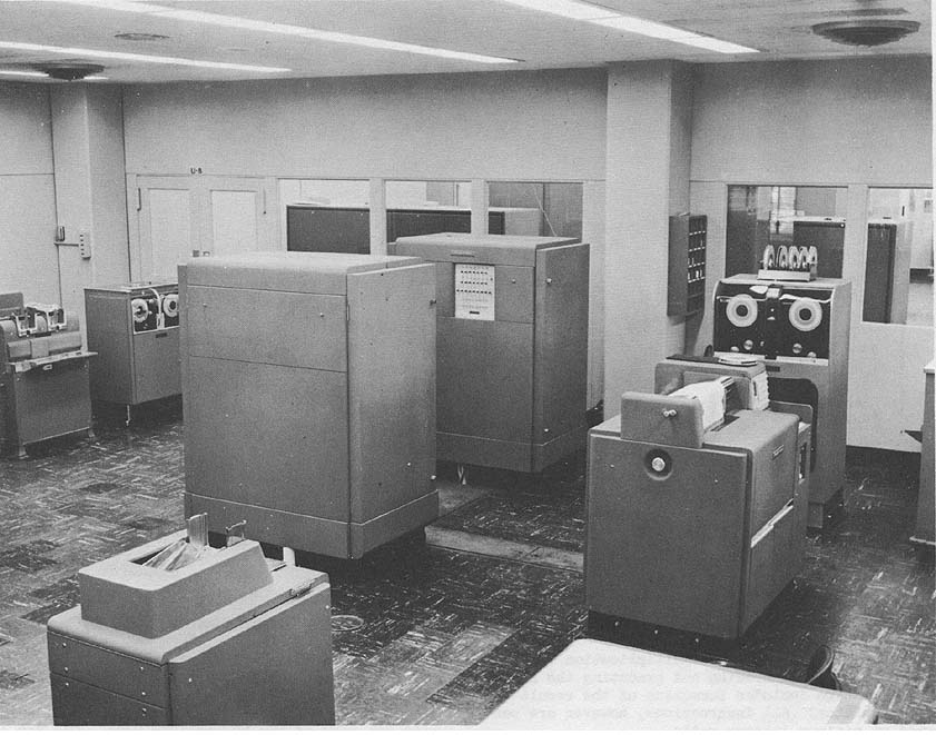
BRL 1961, UNIVAC II, start page 0994
|
Photo by Great Northern Railway Company
Addition, subtraction, and multiplication times given below
include reading and executing the instruction. The time includes
formation of the result in the accumulator. All instructions,
however are performed at minimum latency rates.
Average Operating Speeds in Microseconds
Addition or Subtraction 200 (11-digit numbers)
Multiplication 1,900 (11-digit numbers)
Division 3,700 (11-digit numbers
Comparison 200 (12-digit numbers
Transfer (Memory to 40/word + 80/instruc-
Register or vice versa)
STORAGE
Manufacturer
Medium Magnetic Core
Capacity 10,000 words 120,000 characters
Memory Locations 0000 - 1999
Access time Zero (Memory references begin dur-
ing "Time Out")
Basic Cycle 20 microseconds
Construction 42 separate magnetic core planes,
each one a rectangle 50 cores wide
and 80 cores long.
Each of the planes is divided into two sections of 50 by 40
cores, making 2,000 cores in each section. Each section contains
one core - for one binary position (bit) - of every one of the
2,000 words. The same relative binary position of the other half-
word is held in a core in the same physical location in the other
section of the plane. Thus each plane contains two binary
positions in each of 2,000 words; the first and 43rd, for example,
or the 9th and 52nd. Physically the memory is a rectangular
prism 7 1/4 inches x 10 inches x 12 3/4 inches.
A memory location thus always implies two cores in all 42
planes. The two cores are determined by the intersection of one
column of fifty possible columns with two rows of the 80
possible rows. One row is in each section of the plane. All 42
planes are used twice for each word.
Associated with the memory is a half-word insertion register of
42-bit capacity. Each bit is temporarily stored in a magnetic core of
this register during a memory reference. Each of these register cores
is associated with one of the 42 memory planes. To write into the
memory, the first half of the word is placed in the insertion register
and the address selector alerts the appropriate column and the
proper row of the top section in each of the 42 planes. At the
appropriate instant the information is transferred from each core
of the insertion register to the selected core in the corresponding
plane of the memory. 42 pulse times later, the second half word has
been placed in the insertion register and the process is repeated in
the lower section of the memory. Read-outs are accomplished in a
reverse manner. The speed of the memory has been adjusted to the
speed of the arithmetic portion of the Univac which permits the
transfer into or out of the memory of 12 characters in 40
microseconds. Word pulses flow from or to the high speed bus and
the insertion register via a mechanism which converts from serial
to parallel and vice versa, in 42 bit modules.
All users utilize a 2,000 word 24,000 digit, magnetic core
storage unit.
Commodity Stabilization Service 16 -
Uniservo II's
|
BRL 1961, UNIVAC II, start page 0995
|
Photo by Great Northern Railway Company
INPUT
Manufacturer
Media
Magnetic Tape (Uniservo II) 20,12.4, or 5 Kc digit
rate; 100 in/sec
Keyboard Manual
Unityper II Manual (50 char/in density)
Card to Tape Converter 240 cards/min (80 or 90
col cards)
Paper Tape to Magnetic 200 char/sec (5, 6 or 7
Tape Converter channel)
Verifier Keypunching (Verifica-
tion of Unityper II Tapes)
The UNISERVO II
Purpose
The Uniservo II transports tape over a standard mag-
netic head (for reading and recording) under the con-
trol of Univac II.
Physical Specifications The Uniservo is housed in a cabinet, the upper
section of which contains the reel mounts and is covered by a removable glass
door. The front panel doors are interlocked such that the center drive is
stopped whenever the doors are opened. The entire front cover is easily
removed, giving access to the loops.
Height 62 inches
Width 30 inches
Depth 30 inches
Working Space 6 ft 5 in x 5 ft 9 3/4 in.
Weight 650 lbs.
Operation
Input Function. A Uniservo may be used to read the coded, magnetic dots on
the tape moving forward or backward and transfer the data in the form of
electronic pulses to Univac.
Output Function. A Uniservo may be used to record the results of Univac
processing in the form of coded, magnetic dots on a metallic tape or a mylar tape
moving forward.
Reel Mounts. The reel mounts hold the standard 6 inch and 8 inch reels
for magnetic tape and an 11 inch reel for mylar tape.
Tape Handling System. There are two independent servo systems - the two
reel motor servos. The center drive is a magnetic clutch and the control signal to
the clutch is supplied by Univac. The tape around the center drive hub is
isolated from the tape reels by two loops of tape. The reel servos are controlled
by loop size detectors.
The mylar spacer used on Uniservo I, has been eliminated on Uniservo II to
accommodate the higher pulse writing density. A new hard surface to minimize
head wear is being provided on Uniservo II.
Standard Magnetic Head. The standard magnetic head reads from or records
in 8 channels. Seven of the channels are used for the 7-pulse code of the Univac
System and the 8th channel is a sprocket channel.
Tape speed. 100 inches per second (nominal). Tape packing density 120
characters/inch.
Magnetic Clutch. Uniservo II is equipped with a magnetic clutch which
provides the following:
Start-Stop time of 5 milliseconds maximum. Reading or writing speed of 51
milliseconds for 720 characters (51 ms maximum to start, read 1 block, and
stop).
�
|
BRL 1961, UNIVAC II, start page 0996
|
Rewind of any number of Uniservos, up to and including 16,
simultaneously.
Safety Switches. The Uniservo is fully equipped with safety
switches which apply brakes to the reels if either of the 2 loops
exceeds the prescribed length.
Control. The control of a Uniservo is maintained by Univac
and exercised during a program by the following types of
instructions: Read Forward Read Backward Record at high pulse
density Record at low pulse density Rewind without interlock
Rewind with interlock
Connection to Univac. As many as 16 Uniservos may be
connected to Univac II at any one time. The connection is made
by means of a sectional trough on the top of the line of Uniservos
and continuing from the first Uniservo of the line to one corner of
Univac. Uniservos may be electrically interchanged without
effecting the program.
Power Requirements The main power for the Uniservos is
supplied by Univac.
USN ESO
Media Speed
Unityper Keyboard
(Off-line: source document/Univac tape)
Card-to-Tape240 cards/min (Off-line)
Uniservo (Tape Station) 25 Kilocycle/sec
(On-line, read operation) Commodity
Stabilization Service Off-line Equipment
1 Card-to-Tape Converter (80 column card)
2 Tape-to-High Speed Printers (600 lpm printers)
1 Bi-directional Paper Tape to Magnetic Tape
(B-PTM-7)
1 Tape Cleaner
2 Unitypers
Metropolitan Life
Medium Speed
Univac Card-to-Tape Converter 240 cards/min
Pacific Mutual
Uniservo II 100 inches/sec
250 char/inch
Very reliable with metallic tape. Input buffering
of 60 words of magnetic core.
USS
Magnetic Tape 250 char/in
100 inches/sec
80-column card to magnetic tape converter. 300 cards
per minute.
OUTPUT
Manufacturer
Media
Magnetic Tape (Uniservo II) 20, 12.4, Or 5 Kc digit
rate
Uniprinter 10 char/sec (20 char/in
density)
High Speed Printer 600 lines/min (130 char
line, maximum)
Tape to Card Converter 120 cards/min (80 col
cards)
Magnetic Tape to Paper Tape 60 char see (5, 6. or 7
Conversion channel
Magnetic Tape to Magnetic 90 char/sec (Speed de-
Tape Transrecorder pendent upon commmica-
tion facilities)
USN ESO
Media Speed
Tape-to-Card 120 cards/min (Off-line)
High Speed Printer 600 lines/min (Off-line)
Uniservo (Tape Station) 2 Kilocycle/sec
(On-line, write operation
Metropolitan Life
Univac Hi Speed Printer 600 lines/min
Univac Tape to Card120 cards/min
Converter
Pacific Mutual
Uniservo II 100 inch/sec
250 char/in
Very reliable with metallic tape.
Output buffering of 60 words of core. Can simultaneously read
on 1 tape handler, write on a second and
be rewinding a third.
USS
Magnetic Tape 250 char/in
100 in/sec
High Speed Printer600 lines/min (Off-line)
Magnetic tape to 80-column card converter - 120 cards
per minute.
CIRCUIT ELEMENTS OF ENTIRE SYSTEM
Tubes 5,200
Tube types 20
Crystal diodes 18,000
Magnetic cores 184,000
Transistors 1,200
Separate cabinets 4
Above figures are approximate and do not include input-
output devices.
CHECKING FEATURES
Checking Circuits Whenever feasible, registers and other
circuits appear in duplicate. Their contents are continuously
compared so that inconsistencies between the data in the identical
units give an indication of faulty operation, and stall the
computer. At this point, the instruction may be repeated. The
pulse code used in the Univac System is so designed that all
characters contain an odd number of pulses. At several strategic
points within Univac, every character is checked for an odd
number of pulses. An indication is given whenever an even
number of pulses is detected, and the computer stalls. Other types
of checking circuits cause Univac to stall when other types of
errors occur.
An error occurs if reference to a non-existent memory address
is attempted.
An odd-even error in the transfer rI to rM will result in a
transfer stop and the location of the error (rI address) will be
indicated.
The 720 character count will be displayed on a modulus
100 counter.
"All ones" checker. In addition to the parity bits check on the
high speed bus, a second checker establishes that the invalid "all
ones" character is not inadvertently created by a system fault.
Input and output checkers also detect the invalid "all ones"
character.
Built-in checking features are contained in the
Card-to-Tape Converter, the Tape-to-Card Converter
and the High Speed Printer.
Fusing
Univac is completely fused in order that faults may
be isolated. Each bay has its own set of fuses in
addition to main fuses on all DC and AC potentials.
�
|
BRL 1961, UNIVAC II, start page 0997
|
If a fuse blows, power is shut off and an indicator
circuit shows in which bay the blown fuse is located,
anda "flag" indicates the specific fuse.
Voltage Monitoring
An automatic voltage monitoring system continuously
monitors all critical DC potentials giving an alarm
if any moves outside the prescribed limits.
POWER, SPACE, WEIGHT, AND SITE. PREPARATION
Manufacturer
Univac has a separate power supply unit. The Univac
II is designed to operate from a power service of
480 volts, 208 volts or 240 volts, three phase, 60
cycle. The system voltage must be specified in ad-
vance in order that the switch gear and 75 KVA trans-
former listed below may be properly supplied.
Power Requirement:
Kw KVA PF
Motor Generator 47.3 59.2 0.8
Heaters 45.0 45.0
Blower Motor 6.1 7.65 0.8
Standby, etc. 2.0 2.0
Uniservo 16 x 1.5 Kw 24.0 30.0 0.8
----- -----
124.7 143.85
Univac II Power System
The electrical power system for Univac II Central Computer and Uniservos
consists of a packaged switchgear unit, a 75 KVA transformer, a 400 cycle motor
generator set and a power supply unit. The power and control installation for the
chilled water system and the peripheral equipment are discussed below. Wiring
between units of the system is to be done by the user.
Switchgear. The switchgear unit controls the incoming power, the motor
generator set supply and 400 cycle output circuit, the filament power and
Uniservo power, and it is the center of all power control circuits. The main line
circuit breaker will be supplied according to the system voltage. The motor
starter will always be supplied for 480 volts. Dimensions: 8 ft 4 in wide; 30 in
deep; 6 ft high.
75 KVA Transformer. A 75 KVA transformer, air cooled type, is supplied for
mounting by the customer. If the system voltage is 480 volts the transformer will
be 480/208 and connected between the main line circuit breaker and the filament
power circuit breaker. If the system voltage is 208 volts the transformer will be
208/480 and connected between the main line circuit breaker and the motor
circuit breaker. If the system voltage is 240 volts the transformer will be +0/480
and connected between the main line circuit breaker and the motor circuit
breaker.
Motor Generator Set. The motor generator set con-
sists of a 75 HP motor and two 25 KVA, 0.9 power
factor 400 cycle generators. The motor is served by
480 volts, 3 phase from the switchgear. The 400
cycle output is controlled by electrically operated
circuit breakers in the switchgear. Control of 400
cycle voltage and excitation for the generators is
by the exciter regulator units in the switchgear.
Base 93 in long x 24 in
Overall 104 1/8 in long x 29 in
Area 15.8 sq ft
Floor loading 284 lbs/sq ft
Space Requirements
Approximate Dimensions
Height 102 9/16 in.
Width 171 3/8 in.
Depth 94 3/4 in.
Working Space 16 ft x 22 in.
Weight 16,000 lbs
Univac contains thirteen bays of chassis. These bays are arranged in a
structure resembling a letter "C". There are two bays at each end, five bays along
one side and four bays and a door allowing access to the interior of Univac
along the other side.
Each bay contains three-tiered sections. Each section contains twelve
removable or plug-in type chassis. The chassis in each bay are accessible through
doors which make up the casework. The core storage sections, however, contain
36 printed circuit chassis.
The inter-wiring between chassis is one the back boards of the sections
and bays and is accessible from inside Univac.
Cooling System Requirements. The heat generated by the 5,200 vacuum
tubes and the electronic components requires a cooling system. The Central
Computer, Uniservos and power supply are cooled by a circulating chilled
water system. 130 gallons per minute of 500 water are required. A three way
mixing valve with controls and a circulating pump are required for the Central
Computer and Uniservos. The power supply unit contains its own control.
Water connections for the power supply may enter the cabinet either at the top
or bottom. Water connections for the Central Computer and the Uniservos are at
the sides near the floor and the piping may be run either on the ceiling or below
the floor.
Refrigeration System Requirements. The Central
Computer, Uniservos, and power supply units require
35 Tons of refrigeration.
USN ESO
Power, computer 190 Kw 190.5 KVA 0.95 pf
Power, air condit 75 Kw 75 KVA 0.9 pf
Volume, computer 1,200 cu ft
Volume, peripheral equip10,560 cu ft
Volume, air cond & cooling tanks 1,200 cu ft
Area, computer 1,636 sq ft
Area, peripheral equip1,056 sq ft
Area, air conditioning450 sq ft
Room size, computer49.5 ft x 33 ft
Room size, peripheral equip32 ft x 33 ft
Room size, air conditioning400 sq ft
Floor loading 20 lbs/sq ft
250 lbs concen max
Capacity, air conditioner75 Tons
Weight, computer 36,000 lbs
Weight, peripheral equip 14,000 lbs
Weight, air conditioner3,000 lbs
Total weight 53,000 lbs
Building modifications consisted of trenching in floors to accommodate
chilled water cooling system and power cables. Water supply and return with
100 ton cooling tower and basin installed on roof of building. 75 ton compressor
to produce cold water for ADP equipment and room air conditioning. Duct work
for room air conditioning is installed in regular ceiling. Existing power facilities
were adequate to assume the load from ADP without modification.
Metropolitan Life
Power, computer 124 Kw 144 KVA 0.86 pf
Power, water cooler 25 Kw
Volume, computer, 1,200 cu ft
16 servos, power units
Area, computer, 16 servos,250 sq ft
power units
Area, water cooler 900 sq ft
Room size 2,000 sq ft
Floor loading 10 lbs/sq ft
284 lbs concen max
Capacity, water cooler 50 Tons per comp.
Weight, computer 16,000 lbs
Weight, water cooler 13,000 lbs
Above figures are for each computer.
�
|
BRL 1961, UNIVAC II, start page 0998
|
Walled room for motor-generator sets and voltage regulators
and switch gear, fenced areas for tape storage, installed separate
refrigeration equipment on 15th floor and water lines to
computers on 20th floor, installed power lines from 15th floor
transformers to 20th floor, dug channels in concrete floor for
lines between electronic units.
Pacific Mutual
Power, computer 150 KVA 1.0 Pf 3 phase
Room size, computer 1,500 sq ft
Floor loading 150 lbs/sq ft
Weight, computer 35,000 lbs
Installed special power lines to fourth floor site from special
switchboard directly from street transformer. False ceiling
primarily for esthetic purposes
Ductsinstalled for room air conditioning.
USS
Power, computer 221 Kw 246 KVA 0.90 pf
Power, air cond 90 Kw 106 KVA o.85 Pf
Volume, computer 70,630 cu ft
Volume, air conditioner28,996 cu ft
Area, computer7,063 sq ft
Area, air conditioner2,636 sq ft
Floor loading250 lbs/sq ft
250 lbs concen max
Capacity, air conditioner148 Tons
25,000 cu ft/min
Converted warehouse to office-type space. Plenum chambers
provided. Complete air filtering and airconditioning. Installed
ceiling lights, wall panels and tiled floor. 440 volt supply to
switch gear. Equipment fed by conduit and cable racks.
COST, PRICE AND RENTAL RATES
Manufacturer (Original Prices)
Base Monthly Rental Outright
1 Shift Sale Price
Description 5 Day Week F.O.B. Factory
Univac II Central Com- $18,540.00 $970,000
puter w/power supply
& supervisory ctl desk
Uniservo II 450.00 20,000
Uniprinter 390.00 22,000
Extra Dolly Assembly for 122.50 7,000
Uniprinter
Unityper II 90.00 4,500
Verifier Not currently available
High Speed Printer 3,300.00 185,000
Card-to-Tape Unit w/47 2,520.00 142,100
character code
Card-to-Tape Unit w/38 2,500.00 ---
character code
Tape-to-Card Unit 2,300.00 130,000
Perforated Tape to 1,800.00 108,000
Magnetic Tape (PTM)
Converter
Magnetic Tape to Perfora- 1,500.00 90,000
ted Tape MTP) Converter
The high speed printer and the card-to-tape unit
with the 47 character code requires a customer fur-
nished voltage regulator. Prices are subject to
change without notice.
Rental charges include maintenance service, spare
parts and test equipment. Separate maintenance con-
tract and maintenance advisory service contract
available to purchasers of Univac Systems.
USN ESO
Prime Monthly Usage Rates
Central Computer w/12 Uniservos $23,940
High Speed Printer 4,250
Card-to-Tape 2,540
Tape-to-Card 2,385
Unityper 9o
Verifier 250
Metropolitan Life
4 Univac II's, ea, with 16 Uniservos, total
$+,035,000.
3 Card-to-Tape Converters 2 Tape-to-Zard Converters, 3
High Speed Printers cost 1,345,000.
1 High Speed Printer rents at $5,000/month.
Maintenance service for 4 Univacs and auxiliaries cost
$52,000/month.
Pacific Mutual
Unitypers, computer, servos and printer cost approximately
$1.5 million.
Maintenance service is performed by own maintenance staff.
USS
Basic system includes two (2) Univac II Computers, twenty-
eight (28) Uniservos, one (1) Unityper, and one (1) Unityper-
verifier.
Additional equipment includes one (1) Card-to-Tape
Converter, one (1) Tape-to-Card Converter, and two (2) High
Speed Printers, with core buffers.
Equipment is rented. Maintenance is performed by the
lessor.
PERSONNEL REQUIREMENTS
Manufacturer The number of engineers, technicians and
operators required depends upon the equipment complement
of the Univac System and the shift operation. USN ESO
One 8-Hour Two 8-Hour Three 8-Hour
Shift Shifts Shifts
U R U R U R
Supervisors 5 5
Analysts 7 8
Programmers 16 20
Clerks 5 5
Librarians 1 1
Operators 2 2 4 4 5 6
Engineers 4 4 6 6 8 9
In-Out Oper 2 2 4 4 6 6
Tape Handlers 1 1 2 2 3 3
The operators include the shift supervisor for each of the 1st
and 2nd shifts.
Engineers are Remington Rand personnel included as part of
the rental contract.
Operation tends toward closed shop.
Methods of training used include 8 weeks of classroom
instruction plus 18 weeks of on-the-job training. Formal
training agreements between ESO and Civil Service
Commission.
Government wages in this line of work are not competitive with
those being offered by ADDS users in industry and/or ADDS
manufacturers. Skilled employees after 18-24 months training and
experience in this field of work are showing a growing tendency to
accept non-government employment.
�
|
BRL 1961, UNIVAC II, start page 0999
|
Metropolitan Life
One 8-Hour Two 10-Hour Shifts
Shift 4 Days/Week
Used Recomm Used Recommended
Supervisors 4 4 6 8
Programmers 6 6
Clerks 12 13
Librarians 3 3
Operators 14
In-Output Opera 24
Tape Handlers 4
Methods of training used includes suppliers classes for
programmers and operators, occasional special classes run by
programming coordinator, and on-the-job training for clerks,
librarians, tape handlers, and in-output operators.
Machines work 20 hours per day, 6 days per week.
Operators work 10 hours per day, 4 days per week. Pacific
Mutual
Three 8-Hour Shifts
Used Recommended
Programmers 26
Librarians 0 1
Operators 5 6
Engineers 9 9
In-Output Opera 4 5
Operation tends toward open shop.
Method of training used is basically on-the-,job training
with some formalized classroom work.
"Typical" personnel is difficult to recommend or give with
great detail due to emphases and approaches to the problem. Each
group must study their own problem and then work out the
personnel set up.
USS
Two 8-Hour shifts
Supervisors 7
Analysts 33
Coders 2
Clerks 4
Operators 5
In-Output Opera 3
Tape Handlers 4
Methods of training used includes equipment manufacturer
schools, internal schools, and on-the-job training.
RELIABILITY, OPERATING EXPERIENCE,
AND TIME AVAILABILITY
Manufacturer
Reliability and operating experience based on the
formula: (Available Operating Time minus Lost Time)
divided by (Scheduled Operating Time). The cumula-
tive performance reports for Univac I Central Comput-
ers have averaged 93.0%.
USN ESO
Average error-free running period 16 Hours
Good time 123 Hours/Week (Average
Attempted to run time136 Hours/Week (Average)
Operating ratio (Good/Attempted to run time) 0.90
Above figures based on period 1 Jul 59 to 30 Apr 60
Passed Customer Acceptance Test 1 Jul 58
Time is not available for rent to outside organiza-
tions.
Computer is normally run for 40 straight hours and then there
is an 8 hour preventative maintenance shift before the next 40
hours.
The 10 per cent lost time includes losses as a result of tape;
computer, operator, program and data error conditions.
Metropolitan Life
Good time102.2 Hours/Week (Average)
includ good rerun time
Attempted to run time112.7 Hours/Week (Average)
Operating ratio (Good/Attempted to run time) 0.91
Above figures based on period from Jan 59 to Jan 60
Passed Customer Acceptance Test May 58
Time is not available for rent to outside organiza-
tions.
These Univacs were acquired under an option to convert
Univac I's to Univac IT'S. The first Univac I was accepted in late
1954.
Pacific Mutual
Good timeapprox 100 Hours/Week (Average
Attempted to run time120 Hours/Week (Average)
Operating ratio (Good/Attempted to run time) About
0.80 and improving.
Above figures based on period 1 Jan 60 to present Passed
Customer Acceptance Test 1959 Time is not available for rent
to outside organizations.
USS
Good time120 Hours/Week (Average)
Attempted to run time137 Hours/Week (Average)
Operating ratio (Good/Attempted to run time) 0.87
Above figures based on period 14 Mar 60 to 9 Apr 60
Passed Customer Acceptance Test May 59
Time is not available for rent to outside organiza-
tions.
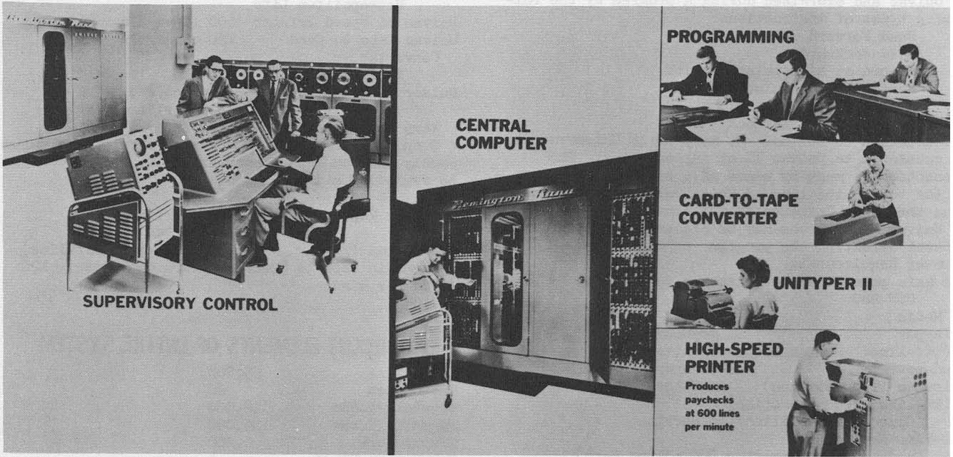
ADDITIONAL FEATURES AND REMARKS
Manufacturer
Buffer Units
Input buffer (rI) 60 words of core storage. Input character
rate up to 40,000 per second - dependent upon speed of
Uniservos.
Output buffer (r0) 60 words of core storage. Output character
rates of 20,000; 12,400; and 5,000 per second.
Transfer buffer (rW) 9 words of core storage. Cooperates with
main memory during V and W instructions to transfer up to 9
words at 25,000 words per second. Transfer buffer (rZ) 60 words
of core storage.
Control of Operation
Univac is controlled by instructions which are recorded on
tape and read into the memory. The instructions are stored in
successive memory locations beginning at 0000. Two
instructions may be stored in each memory location.
Simultaneous reading, writing and computation are possible due
to built-in buffer units. Univac can read from one Uniservo, write
on a second and rewind all other Uniservos simultaneously. Unless
there is another read, write or rewind instruction immediately
following, Univac may continue to compute while reading,
writing and rewinding operations are being performed.
Univac starts operating in accordance with the instructions
stored in memory location 0000 aims refers automatically to
suceeding memory locations. Certain of the instructions read
from the tapes the source data upon which the instructions
operate and store the source data in the memory. Other
instructions cause Univac to record the results of the operations
on tape.
The operation of Univac is controlled by automatic
sequencing. It may be interrupted by instructions that transfer
the control of Univac from one memory location to another
memory location not in sequence. This mode of operation
conserves space in the memory
�
|
BRL 1961, UNIVAC II, start page 1000
|
and requires a sub-routine to be stored only once in any part of
the memory.
New Instructions
But for several minor exceptions, Univac II executes all Univac
I instructions in exactly the same manner as Univac I. Certain of
these instructions, however, have been assigned new functions
which serve to extend their overall flexibility. The V instruction,
for example, will now transfer from one to nine words instead of
merely two as was formerly the case, and the Y-Z instructions will
now transfer groups of words ranging from ten to sixty in number
in steps of ten words. Formerly, ten words and only ten words
could be transferred when using this instruction. As a further
example of the greater flexibility permitted in Univac II, the
extract function (or E instruction), formerly limited to register A,
has been generalized so that it now covers all instructions which
read out of the memory (A, B, D, L, M, N, P and S). The EF
instruction permits recombination of selected characters from
register A with the remaining characters of the word in memory
location. Instruction A has been extended in usefulness also, and in
addition, an I instruction (transfer from register L to memory) has
been adopted as a standard command.
Overflow
With Univac II the addition of a 1 to the control counter
reading following overflow is automatic. When using Univac I
programs on Univac II a special switch will inhibit the addition
of 1 to the control counter reading following overflow and cause
the 3rd instruction digit to be interpreted in the memory switch
as a decimal zero regardless of its actual value. Therefore, in
Univac I programs where the 2nd and 3rd instruction digits have
been used for overflow control, the presence of these digits will
not influence the execution of the instruction.
Compatability Switch
A switch provides three circuit corrections to promote
compatibility of Univac I and II programs. Any other
incompatibility will require program corrections. With the switch
in position to handle Univac I programs, the Univac II will treat
the 3rd instruction digit as zero, for V, W, Z and Y instructions,
treat the 2nd instruction digit as zero and restore the Univac I
mode of overflow action on the control counter.
Tape Handling Operations
As many as 16 Uniservos may be connected to Univac by a
metallic duct carrying the necessary cables. Univac can read from
tapes mounted on these Uniservos with the tapes moving forward
or backward. Univac can record on a tape moving forward. It can
read from one Uniservo, write on a second and rewind all other
Uniservos simultaneously. Unless there is another read, write or
rewind instruction immediately following, Univac may continue
to compute while the reading, writing and rewinding operations
are being performed.
Tape recording for Univac II must be done according to the
following:
Spacing per block 4.60 in
(with 1 in between blocks) (3.60 in per block)
Pulse density per inch 200 nominal
Blocks per reel 4,000 (metallic) nominal
Read time per block 51 msec. minimum
(metallic and mylar)
Per reel 3.4 minutes minimum
(metallic)
Rewind time per reel 3.1 minutes (metallic)
Feet utilized 1,535 ft metallic)
2,400 ft (mylar)
PROGRAMMING SPECIFICATIONS
Library and compiler routines for mathematical and
commercial use, and service routines for maintenance uses, are
available to the customer.
Modified or Added Instructions
I instruction providing for transfer of information from
register rL to memory.
Field selection as specified by a second instruction digit F. For
the instructions A, B, D, L, M, N, P and S it operates so that
the word transferred from memory location M contains only
those digits from the columns of "m" which correspond to the
columns in register F containing "odd" characters. The
remaining column positions of the word, transferred from "m"
to the receiving register contain decimal zeros.
The EFm instruction permits insertion into a word in memory
location "m" of the characters in those columns of register A
which correspond to the columns containing "odd" characters in
register F. "Odd" characters in the Univac code have a binary
zero in the least significant binary position. rA will also contain
the complete word which is restored at memory location "m".
Add to memory. The add to memory instruction is effected by
adding a special designator (H) in the 2nd digit position of the A
instruction. It results in the execution of an A instruction
followed by an automatic H instruction. Register rA will retain
the total (rX + rA) at the conclusion of the add to memory
instruction. An equivalent subtractive operation is performed by
the SH instruction.
Multiple Word Transfer
The Vnlml, Wn2m2 word transfer instructions
transfer one to nine words as specified by the numeric (n) appearing in
the second digit position. Register rW provides the transfer
storage. The transfer is made using V and W instructions as for
Univac I except that no reversal of position occurs in a 2 word
transfer as may in Univac I. Note also that if the second digits of
the V and W instructions are not equal special transfers result. If
nl > n2. The first (nl - n2) words transferred from ml to rW are
not transferred from rW to m2. If nl < n2. The
(n2 - n1 ) words transferred to rW by a previous V instruction are
transferred to m2 followed by the nl
words of the current V instruction. When n = 0 the instruction
will be processed as a skip instruction.
The Ynlm1 , Zn2m2 pair of instructions permits the transfer.
groups of 10, 20, 30, 40, 50, or 60 words as designated by a
numeric (1 through 6) in the second digit position of the
instruction. The Y, Z instructions use rZ as transfer storage. If
the second digits of the Y and Z instructions are not equal, special
transfers result. If nl > n2. The first nl - n2) tens of words
transferred from M1 to rZ will not be transferred to M2. If nl <
n2. The (n2 - nl) tens of words transferred to rZ by a previous Y
instruction are transferred to m2, followed by the nl tens of
words of the current Y instruction.
When n = 0, 7, 8, or 9, the instruction will be processed as a skip
instruction.
Tape Writing Density Controls
5nm instruction causes writing of 200 pulses per inch except
that manual countermanding pushbuttons will be provided to
select one or more Uniservos on which the 5nm instruction
will be interrupted as
|
BRL 1961, UNIVAC II, start page 1001
|
calling for a 124 pulse per inch writing density. These manual
pushbuttons will be in addition to those available for block
subdivision and delta (A) second digit decoding of in/out
instructions.
7nm instruction causes writing at 50 pulses per inch. Block
subdivision controls will operate as in Univac I with all densities.
Block divisions (space between blocks) will be 1 inch except for
the 124 ppi density. This will be 2.4 inches.
Memory Clear
A protected switch will provide for memory clear (rM) to
decimal zero. Register rM will clear on read-in.
Buffer Register Clear
Registers r0, rI, rZ and rW clear only on read-in.
Instruction Execution Time
Basic machine cycle is reduced from four to three cycles (a
cycle is omitted).
All instructions are performed at minimum latency rates.
USN ES0
Outstanding features include self-checking of the computer
through use of duplicate circuitry in both the arithmetic and
logical units.
Standard tape labelling techniques are used; storage, shipping,
protection from humidity, temperature and physical handling
problems are minimal. System operates with metallic magnetic
tape. Back-up master tape files are stored in a remote location as
protection against loss of information through electrical, fire or
other damage to the tapes stored in computer center library.
This activity has experienced a high performance rate in the
use of metallic magnetic tape with its ADP system. A number
of tests have been made with various types of mylar base tape;
but, to date, the performance of mylar tape on Univac II is
unsatisfactory.
Metropolitan Life Outstanding features are that the
system is completely self checking and simple to operate. Each
tape is kept in a cardboard box, labeled on the reel and on the
edge of the box, stored like books on open shelving with stall.
dividers every three reels, in locked fenced-in area. No special
humidity, fire, or dust protection needed for metal tapes.
Pacific Mutual
Outstanding features include self checking and duplicated
circuitry affording basically error free output. The Unitypers
allow a complete tape system, completely devoid of any type
of punch card.
If anything, we have erred in over controlling for everything
except humidity, which we do not control.
We feel that for our ,fob we have the best equipment presently
available and are trying to keep aware of the next generation.
USS Metal cases are used for ordinary filing. Fireproof
cabinets for some master tapes.
PRODUCTION RECORD
Number of systems delivered 32
FUTURE PLANS
USN ESO
No new components or modifications to the installed ADP
system are contemplated by this activity.
It is planned to retire the present ADP system and replace it
with a more powerful, solid-state ADP system during FY 1962.
Several new applications will be programmed for processing,
in addition to the applications already in production on the
present ADPs, at such time as the replacement system is
installed. Metropolitan Life
Plan to get from two to four more systems of the 3rd
generation type such as Honeywell 800, IBM '080, etc.
Plan to extend tape files from present 6 million policies, to
include other types for about 40 million policies, and expect to
run these files daily instead of bi-weekly, and extend the area of
operations performed.
Plan to be installing in many areas of work ,previously
deferred because of lower expected savings and/or greater
planning effort. Pacific Mutual
We have gone from Univac I to Univac II and anticipate
moving to Univac IIII - IBM 701 - Datamatic 801RCA 501 or
some other system as soon as the new generation of computer
renders ours so obsolete as to be impractical to retain. This could
conceivably be in 1963, 64 or 65.
We are continually investigating, modifying, etc., our system
and equipment and looking to add new applications. USS
Additional applications of the same type as currently processed
will be installed.
New systems being reviewed and evaluated for
consideration.
INSTALLATIONS
U. S. Navy Electronics Supply Office Great
Lakes, Illinois
U. S. Department of Agriculture
Commodity Stabilization Service
Kansas City, Missouri
Metropolitan Life Insurance Company (3) 1
Madison Avenue New York 10, New York
Metropolitan Life Insurance Company (1) 315
Park Avenue So. New York City, New York
Pacific Mutual Life Insurance Company
Pacific Mutual Building Los Angeles, California
United States Steel Corporation 1509
Muriel Street Pittsburgh 3,
Pennsylvania
U. S. Department of Agriculture
Kansas City Commodity Office
Kansas City, Missouri
�
|
BRL 1961, UNIVAC III, start page 1002
|
UNIVAC III
Univac III Data Processing System
MANUFACTURER
Remington Rand Univac
Division of Sperry Rand Corporation
Photo by Remington Rand Univac, Division of Sperry Rand Corporation
APPLICATIONS
System is designed for commercial data processing as well as scientific
applications. The UNIVAC III is a medium-cost, high performance electronic
data processing system designed to meet the broadest possible needs of
business and science. The magnetic core memory holds from 8,192 to 32,768
words in increments of 8,192 words each with a cycle time of 4.5 microseconds.
Words can be pure binary, binary coded decimal, UNIVAC Xs-3, or any other
form. UNISERVO III tape units allow reading, writing, and computing
simultaneously. The read-write rate is 200,000 digits per second.
Up to thirty-two Uniservo III tape units and six Uniservo II tape units are
possible. Auxiliary online units may include card-readers which operate at a
rate of 700 cards per minute, high-speed printers at 700 lines per minute, card
punch units at 300 cards per minute, mass storage and other devices. The
UNIVAC III is compatible with other UNIVAC tape
units or with those of other manufacturer.
PROGRAMMING AND NUMERICAL SYSTEM
Internal number system Binary or binary coded dec
Binary digits/word 24
Decimal digits/word 6
Alphanumeric char/word 4
Instructions per word 1
Instructions decoded 75 (approx)
Arithmetic system Fixed point
Instruction type one-plus-one
Number range
Binary +- (296 - 1)
Decimal +- (1024 - 1)
�
|
BRL 1961, UNIVAC III, start page 1003
|
Instruction word format
+--------+--------------------+-------+-------+--------+---------+
| Parity | Indirect Address | IR | Oper | AR/IR' | m |
| | or Field Select Op | | Code | | Address |
+--------+--------------------+-------+-------+--------+---------+
| 27 26 | 25 | 24 21 | 20 15 | 14 11 | 10 1 |
+--------+--------------------+-------+-------+--------+---------+
Automatic built-in subroutines includes automatic interrupt.
Automatic coding includes COBOL and assembly system.
Registers includes four accumulator registers, fifteen index registers, and
thirteen memory address counters.
All instructions are automatically modified by the Index Register
designated. System is able to select as an operand from one bit to ninety-six
bits through use of a field select control word. From one to fourword operands
are possible.
All users of UNIVAC III will be provided with a comprehensive
programming package. The initial pack will contain COBOL, SALT Assy
(Symbolic Assembly Language Translator), sort and merge generators, and an
executive routine including contingency and error check routines.
ARITHMETIC UNIT
Incl Stor Access Exclud Stor Access
Microsec Microsec
Add 8 8 6+6 Digits
Mult 48-724 48-124 6x6 Digits
Div 68-144 68-144 6/6 Digits
Arithmetic mode Serial by digit
Parallel by bit
Timing (Computer) Synchronous
Operation (System) Concurrent
The computer instruction execution cycle is such that the effective
access time is zero.
STORAGE
No. of Decimal Access
Media Words Digits Microsec
Core 32,768 196,608 1.07
Drum (Mass Memory) 4,000,000/Drum 24,000,000 385
Magnetic Tape
No. of units that can be connected 32 Units
No. of chars/linear inch 1,333 Char/inch
Channels or tracks on the tape 9 Tracks/tape
Blank tape separating 0.68-0.78 Inches
Tape speed 100 Inches/sec
Transfer rate 133,300 Chars/sec
Start time 6.3 Millisec
Stop time 6.3 Millisec
Average time for experienced
operator to change reel of tape 30 Seconds
Physical properties of tape
Width 0.5 Inches
Length of reel 2,400 Feet
Composition Mylar
In addition to the units described above, a maximum of 6 Uniservo II may be
included in the system. Check during writing on Uniservo III. Digital
representation (4 bits) 200,000 pulses/sec transfer rate, 2,000 digits/inch.
INPUT
Media Speed
Cards 700 cards/min
80 or 90 column. No plugboard
Uniservo III200 pulses/sec (Digital)
Up to 32 in system
133.3 (Alphanumeric)
Parallel read-write
Uniservo II 25 pulses/sec (Alphanumeric)
For compatibility with other Univac Tape Systems
Paper Tape]
OUTPUT
Media Speed
Cards 300 cards/min
80 or 90 column. No plugboard
Card Printing Print - 900 lines/min
Punch Punch - 150 cards/min
Punches and prints same card in one pass.
High Speed Printer 700 lines/min
Editing program controlled.
Paper Punch
CHECKING FEATURES
Modulus 3 word parity checking, arithmetic, transfer and comparison
operations, and logical checks.
POWER, SPACE, WEIGHT, AND SITE PREPARATION
Power, computer 75.2 Kw 94 KVA 0.80 pf
Volume, computer 900 cu ft
Area, computer 1,500 sq ft
Room size 43 ft x 43 ft x 12 ft
Floor loading 200 lbs/sq ft
1,100 lbs concen max
Weight, computer 27,225 lbs
Heat exhaust vents should be located at roof of each unit. Air
conditioning output ducts should be near unit inlet vents. Total input line
current 261 amperes/line. Recommended main circuit breaker 400
amperes/line. 115 volt convenience outlets should be located every 6-8 ft
approximately 2 1/2 ft off floor.
These figures include the Univac III large system w/16 tape.
PRODUCTION RECORD
Number on order 25
Time required for delivery 18 months
�
|
BRL 1961, UNIVAC III, start page 1004
|
COST, PRICE AND RENTAL RATES
Basic System Units Price Monthly Rental
Computer - 8 K Memory $390,000 $ 8,000
High Speed Reader 35,000 750
Punch Unit 40,000 850
High Speed Printer 79,000 1,650
Uniservo III Synchron- 145,000 2,900
izer-Max. 16 Uniservos
Uniservo III Power Supply 17,500 350
Uniservo III 24,000 ea. 500 ea.
Additional Equipment Units
Card Punching Printer $ 197,500 $ 4,300
Uniservo 11 20,000 450
Uniservo II Synchronizer 92,500 1,925
Uniservo II Power Supply 17,500 350
Memory-Add. 8 K - 67,500 1,400
Add. 24 K 193,500 4,030
Second Uniservo III 145,000 2,900
Synchronizer or Mass
Memory Device
Maintenance/service contracting is included in rental
price.
PERSONNEL REQUIREMENTS
Training made available by the manufacturer to the user includes a program-
systems course for experienced programmers of 5 weeks duration and for
inexperienced programmers of 8 weeks duration.
RELIABILITY, OPERATING EXPERIENCE,
AND TIME AVAILABILITY
The system is completely self-checking.
ADDITIONAL FEATURES AND REMARKS
Outstanding features are modularity, field selection, multiple word operand,
index registers, scatterread-gather write, and indirect addressing.
Unique system advantages includes automatic interrupt, combined with
above features.
The normal procedures for handling Mylar tape may be used.
A one addressable modulus 24 hour clock is included. It keeps time in tenths
of a second and has a digital output which can be read by the computer program.
As faster components become available and more powerful input-output units
are developed, they will be incorporated in this system without requiring
program changes.
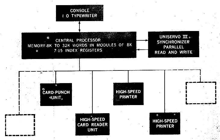
Typical Basic, System
Diagram by Sperry Rand Corporation, Remington Rand Univac Division
�
|
BRL 1961, UNIVAC III, start page 1005
|
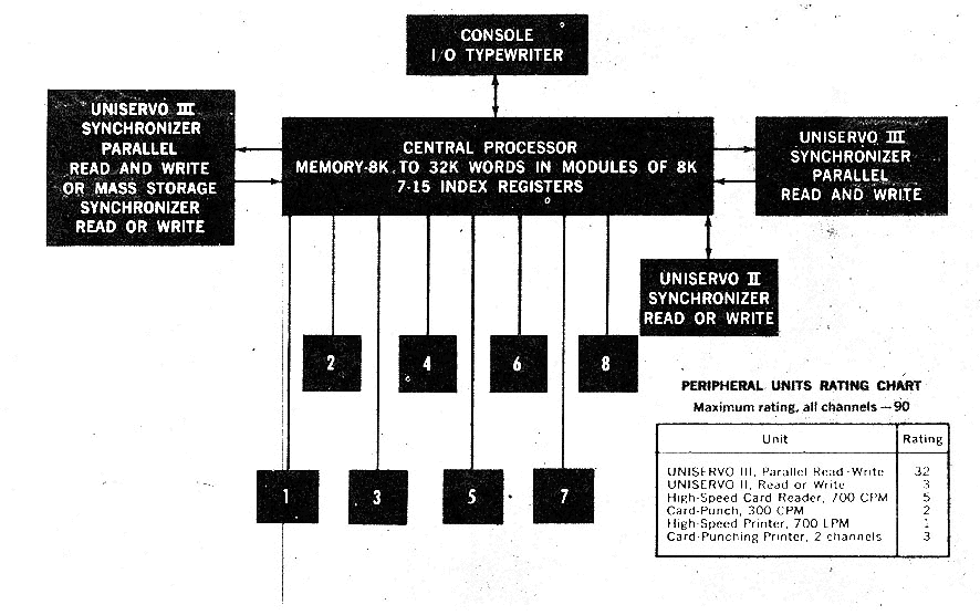
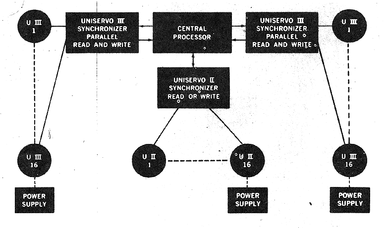
Typical Expanded System
Tape Line Configurations
Diagram by Sperry Rand Corporation, Remington Rand Univac Division
�
|
BRL 1961, UNIVERSAL DATA TRANS, start page 1006
|
UNIVERSAL DATA TRANS
Universal Data Transcriber
MANUFACTURER
Naval Weapons Laboratory
Dahlgren, Virginia
Photo by U. S. Naval Weapons Laboratory, Dahlgren, Va.
APPLICATIONS
Located at the Naval Proving Ground, the system is used for conversion of
scientific or management data from one medium or format to another, primarily
in the processing of input and output for the NORC or other computers.
PROGRAMMING AND NUMERICAL SYSTEM
Internal number system Binary
Binary digits/word 36
Binary digits/character 8 + 1 check bit
Instruction word format
+-----------+---------------------+---------+-------+
| MO | Ml | M2 | M3 |
+-----------+------------+--------+---------+-------+
| 8 1 | 8 6 | 5 1 | 8 1 | 8 1 |
+-----------+------------+--------+---------+-------+
| Operation | B-Register | Address Specifi- | Limit |
| Code | Specifics- | cation of Refer- | Value |
| | tion | ence to Memory | of Bx |
+-----------+------------+------------------+-------+
Since there are no multiply or divide orders, the
operating binary point may be considered to be in any
convenient location. The carry (borrow) bit may be propagated from character to
character in addition (subtraction) with use of double precision orders. A
single reference to the memory brings out four characters designated as M0, Ml,
M2, and M3 into the memory register. Addresses evenly divisible by four
always correspond to the character read out as M0. Instruction words consist of
the four characters M0, Ml, M2, and M3. Instruction words are logically divided
into 4 fields as shown above, namely: Operation Code, B-Register specification,
Address Specification of reference to memory and the Limit Value of Bx.
The operation of the system depends upon the microprogramming of the
computer to generate special orders which will transfer data from the particular
external input device currently in use to the computer memory and from the
memory to the external output device currently in use. The use of micro-
programming, which is accomplished by use of a plugboard, allows an efficient
transfer of data between the computer memory and the external devices with a
minimum of special equipment. Conversion of the data within the memory from
one form to another is accomplished by
|
BRL 1961, UNIVERSAL DATA TRANS, start page 1007
|
the use of an appropriate stored program. This gives a very
flexible system since all that is required to change the system from
one job to another is to change the connections to the external
equipment, insert a different plugboard, and load a new program
into the computer memory. This system was conceived, designed
and is under construction by the Computer Research and
Development Branch of the Computation and Exterior Ballistics
Laboratory of the U. S. Naval Proving Ground, Dahlgren, Virginia.
The system registers are:
1 Input register
1 Output register
2 Computing registers
6 B-registers (address modifiers)
1 Instruction register
1 Instruction counter
Indicator latches (single bit registers)
Other special registers
External devices communicate with the computer via the input
and output registers under control of the computer. The input
register can select at high speed from either of two different
external devices. The output register is normally connected to
only one unit. Indicator latches are used both to control the
external devices and to signal the condition of the external devices
to the computer. Special electronic signal generating equipment
tailored to each type of external device is used to facilitate
communication with the input register, output register, indicator
latches and the external device.
ARITHMETIC UNIT
Operation time, incl 1 memory access 11 microsec
Operation time, incl 2 memory accesses 21 microsec
Two memory accesses are required for such orders as read
out and store orders.
STORAGE
No. of No. of Access
Medium Words Digits Microsec
Magnetic Core 2,048 36 bits/word 10
INPUT OUTPUT
Media Speed
Magnetic Tape (NORC) 70,000 dec dig/sec
Magnetic Tape (Potter 906) 37.5/75 in/sec
200 char/inch
Paper Tape (Digitronics) 300/600 char/sec (read)
Paper Tape (Teletype) 60 char/sec (read)
Paper Tape (Flexowriter) 10 char/sec (read)
Paper Tape (Teletype) 60 char/sec (punch)
Paper Tape (Flexowriter) 10 char/sec (punch)
Magnetic Tape (Analogue, Ampex Model FR-100A)
Speeds are 1.875, 3 75, 7.5, 15, 30 and 6o in/sec.
Cards (Remington Rand) 450 cards/min (read)
Cards (Remington Rand) 100 cards min
Cards (IBM Model 101(1 450 cards/min (read))
Cards (IBM Model 514) 100 cards/min (punch)
Typewriter (Flexowriter) Keyboard entry)
Typewriter (Flexowriter) 10 char/secprint)
CHECKING FEATURES
The computer has automatic circuitry built into the system to
check the accuracy of its operation. This check adds a parity bit
to the 8 bits in each character so that the modulo two sum of the
binary one's of these 9 bits is always odd. This check bit is
generated after data enters the input register, is corrected as the
characters are modified by various orders, and is stored in the
memory along with the character. An automatic check is made
for the presence of the proper parity count as the data is
transferred from the memory into the working registers or the
instruction register. The values in the B registers are checked
automatically as they are used and there are checks on the
execution of the overlay and shifting operations in the
computing registers.
Whenever possible checks will be made on the accuracy of data
transmission between the computer and the external devices. For
example, in card reading, data will be loaded into two independent
shift registers from two reading stations, and after the card images
are assembled in memory they will be checked against each other.
In punching data into cards, the card will be read back into the
computer after being punched and this card image will be checked
against the card image sent out to the punch. When magnetic
tapes are written the data will be read back into the computer and
a check will be made on the correctness of the data.
POWER, SPACE, WEIGHT, AND SITE PREPARATION
Power, computer 5 Kw 6 KVA0.83 Pf
Room size, computer 480 sq ft
No special preparation. Air conditioned as a small part of a
large system.
PRODUCTION RECORD
Number produced 1
Number in operation 1
COST, PRICE AND RENTAL RATES
Total approximate cost $350,000 for all units listed except
IBM 101 and 514, which are rented.
PERSONNEL REQUIREMENTS
Three 8-Hour Shifts
Programmers 3
Operators 4
Engineers 1
Technicians 1
Operation tends toward closed shop.
Methods of training used is on-the-job.
�
|
BRL 1961, UNIVERSAL DATA TRANS, start page 1008
|
RELIABILITY, OPERATING EXPERIENCE,
AND TIME AVAILABILITY
Time is available for rent to qualified outside organizations. System has been
in. use on several projects since January 1960. Some engineering work
continues. It may be used by government agencies or contractors when time is
available.
ADDITIONAL FEATURES AND REMARKS
The most outstanding difference between the computer of the Universal Data
Transcriber and any other single address binary computer is the availability of
the plugboard and the plugboard instructions. The plugboard is divided into
three regions. The first region consists of information coming from equipment in
the computer to the plugboard. This includes all of the registers, such as
Register 1, Register 2, Input Register, Output Register, Instruction Register,
Instruction Counter, B7, and the indicator latches, plugboard instruction
specification and the internal clock. Also in this region are external inputs from
the various input and output devices which have been converted to the proper
signal levels. The second region of the plugboard consists of a set of
approximately 75 logical packages. These packages are identical to those used
in the construction of the rest of the computer. In the third region of the
plugboard are exists from the plugboard of the control lines in the computer.
These lines control the transfer of data from "register to register", use of the B
Registers, controlling memory cycles, setting of indicator latches, shifting
various registers, etc. Thus by using all three regions of the plugboard almost
any conceivable (or desirable) cycle of actions can be controlled from the
plugboard. This feature is primarily for use with external devices to get data to
or from them and the memory of the UDT.
The indicator latches in the computer are used primarily for communication
between the UDT and external devices. For example, some of the indicator
latches could be wired, via the plugboard, to control the stopping, starting,
or reading or writing of a tape unit. Other indicator latches could be used to
indicate to the UDT that an external device is in certain conditions, for
example, that a card reader is moving cards, or ready to scan one row of
information, or that it is out of cards, etc. Thus the program can control
external devices, and external devices can be sensed by the program by use of
the indicator latches.
Another feature of the UDT is the "Program Interrupt" ability. If a particular
exit on the plugboard is energized the computer will go into a program
interrupt cycle. This exit can be energized from an indicator latch, or
combinations of indicator latches and various conditions by wiring on the
plugboard. When this condition occurs the computer will automatically make
a program transfer to instruction location 4 at the end of the current
instruction. The address (Y) of the instruction which would have normally
been executed next, if the program interrupt condition had not occurred, will
be automatically stored in character locations 1 and 2 in a form so that if the
character in location 0 is the code for a program transfer (jump) command and
the instruction at location 0 were to be executed, the computer would jump to
the proper address (Y). When this feature is used the program, starting at
location 4, must be suitable to take the appropriate
action for the condition which caused the jump. After this is done, the program
would normally remake the appropriate registers, and then jump to location 0,
which would cause the jump back to the main program at the proper place. By
using this feature the computer can react rapidly to external control information
without requiring repeated sensing on the condition.
The major advantage of the Universal Data Transcriber is its flexibility. It is
not tailored to any specific computer or type of data conversion and is therefore
not likely to become obsolete as fast as many specialized converters. The micro-
programming and stored program features makes it easy to implement almost any
desired conversion with a minimum of engineering effort and special equipment.
The major disadvantage to this approach is that it is more expensive than any
single specialized converter.
To establish the capabilities of the Universal Data Transcriber several
preliminary programs have been prepared. One program for converting 80 colon
alphanumeric IBM cards to NORC magnetic tape provides for arbitrary code and
format conversion, specified by header cards, and converts data to magnetic tape
at a rate of 450 cards per minute. Similar programs have been developed for
conversion from one magnetic tape system to another. If there is a conversion in
both the code representation of the data and in the format, but not in the number
base, the system can convert 4, 5, 6, 7, or 8 bit characters from one form to another
at a rate of approximately 3,000 characters per second. Conversion can be made
from 48 bit binary words to decimal digit words at a rate of approximately 16
words per second. Conversion can be made from 13 digit decimal words to binary
words at rates in excess of 50 words per second.
The Universal Data Transcriber is being designed and constructed at
the U. S. Naval Proving Ground, Dahlgren, Virginia. Subcontractors are
providing the memory, logical building blocks, and various specialized
input and output circuitry.
The logical building blocks are all transistorized megacycle SEAC type
circuitry built by Computer Control Company. Some of these are being modified
to provide two phase operation where the extra speed is required. The memory is
an all transistorized magnetic core memory with a full read-write cycle time of 10
microseconds, and operates in parallel on a 36 bit word or 4 characters of 9 bits
each. The 80brush reading station of the IBM 101, used as a 450 card per minute
reader, will load the data from a row in the card in parallel into a magnetic shift
register which will be shifted into the computer on four wires in 600
microseconds. A similar circuit will be used on the second reading station so as
to provide a check on the reading. Data is punched into IBM cards at 100 cards
per minute by serially shifting, one bit at a time, at a 100,000 cycle shift rate, the
80 bits in the row to be punched. This shift register will pick up relays which
will control the punch magnets in an IBM 514. The reading station which
follows the punching station will be equipped with magnetic shift register for
reading back the data from the punched card for a check. The same shift register
and relays which are used in punching is 120 bits long so that it can be used to
control the printing on an IBM 407. A Flexowriter is perma nently attached to
the system to provide communication between the computer and the operator
and is used as an input for the program tapes, and as an input or output of 5, 6, 7
or 8 channel paper tape. A NORC magnetic tape unit is used to provide
communication
|
BRL 1961, UNIVERSAL DATA TRANS, start page 1009
|
to or from the Naval Ordnance Research Calculator.
INSTALLATIONS
Computation and Analysis Laboratory Naval
Weapons Laboratory Dahlgren, Virginia
�
|
BRL 1961, VERDAN, start page 1010
|
VERDAN
Autonetics VERDAN MBL-D9A Computer
MANUFACTURER
Autonetics
Division of North American Aviation
APPLICATIONS
The computer is used in real time control systems, such as inertial
navigation, bombing, weapon system central digital computer, flight control,
ground checkout and alinement, and process control.
As a data system, it is used for scientific computation, impact predicition, and
mission readiness.
The VERDAN computer consists of three interconnecte computational
centers: (1) an incremental or DA section (2) a whole valve or GP section and
(3) an input-output section. All three centers may be operated simultaneously.
The GP section directs all computation.
PROGRAMMING AND NUMERICAL SYSTEM
Internal number system Binary
Binary digits/word 24
Binary digits/instruction 22
Instructions/word 1
Instructions decoded 52
Arithmetic system Fixed point
Instruction type One and 112 address format
Number range As an integer: -(223 <= W < (223-1)
As a fraction: - 1 <= W < 1 - 2-23
Instruction word format
+----------+----------------+-----------+---------+--------+
| 0 1 | 2 8 | 9 12 | 13 16 | 17 23 |
+----------+----------------+-----------+---------+--------+
| Not Used | Sector of Next | Operation | Channel | Sector |
| | Instruction | Code +---------+--------+
| | | | Operand Address |
+----------+----------------+-----------+------------------+
ARITHMETIC UNIT
Incl Stor Access Exclud Stor Access
Microsec Microsec
Add 160 80
Mult 2,000
Div 2,000
Construction (Arithmetic unit only)
Transistors 1,500
Diodes 10,670
Resistors 4,500
Arithmetic mode Serial
Timing Synchronous
Operation Sequential
The clock rate is 332.8 kilocycles/sec. Above
information is for the G. P. only.
STORAGE
No. of Bin
Medium No. of Words Digits/Word
Rotating Disc Memory 1,664 24
The average access time is one half of a disc revolution, or 5 milliseconds.
Magnetic tape is under development.
INPUT
Media Speed
16 DC Voltages 100 times/sec
(+- 0.5% Range +-lOV)
3 Ternary Coded Pulse 800 times/sec
(using 8 integrators)
32 Shaft Encoder 100 times/sec
(20 significant bits)
3 Resolver Incremental 800 times/sec
(using 8 integrators)
Tape Reader
Manual Control
OUTPUT
Media Speed
15 DC Voltages 100 times/sec (¤0.5% Range ¤lOV)
Serial Digital 332.8 bits/sec
16 Shaft Encoder 100 times/sec (20 significant bits)
4 Bin Code 100 times/sec
4 Ternary Code 100 times/sec
Nixie Display on control panel
Paper Tape Punch5 channel
Typewriter
CIRCUIT ELEMENTS OF ENTIRE SYSTEM
Type Quantity
Diodes 10,000
Transistors 1,500
Capacitors 670
Resistors 4,500
CHECKING FEATURES
Parity on input-output. The same problem can be run on GP and DDA
internally and answers compared.
POWER, SPACE, WEIGHT, AND SITE PREPARATION
Power, computer 0.320 Kw 0.8 pf 400 cycle, 3 phase
Volume, computer 1.4 cu ft
Weight, computer 82 lbs
Air conditioner is not normally required if input air is between OoF and
90oF. Blower must be supplied by user.
PRODUCTION RECORD
Number produced to date 180
Number in current operation 180
Number on order 883 (approx.)
Anticipated production rates 5/week
Time required for delivery 10 months
|
BRL 1961, VERDAN, start page 1011
|
COST, PRICE AND RENTAL RATES
Basic system consists of the computer - VERDAN, manual control panel, and
paper tape reader. Additional equipment includes paper tape punch, tape prep.
equipment, test equipment - C297A, and typewriter. Prices are available upon
formal request to Autonetics.
PERSONNEL REQUIREMENTS
This computer was primarily designed for unmanned control systems and
thus can operate for long periods of time unattended.
Training made available by the manufacturer to the user includes
programming course and operation and maintenance course.
RELIABILITY, OPERATING EXPERIENCE,
AND TIME AVAILABILITY
Calculated mean time before failure, from parts count, is 160 hours. Realized
MTBF under steady state operation is 250 hours.
ADDITIONAL FEATURES AND REMARKS
outstanding features include multiple input-output, combination
GP/DDA, and small size.
Due to the manner in which. the inputs and outputs are handled - internally -
the computer does not halt while inputing or outputing, thus the GP, DDA
and input-output operations can proceed simultaneously, making this machine
almost ideally suited to the real-time control problem.
The VERDAN contains a non-volatile magnetic memory. Provisions are
incorporated such that in case of power failure, all intermediate information is
stored on a memory channel. Upon resumption of power, the flip flops and
registers etc., are reset and the program computation resumes at the point of
interruption.
FUTURE PLANS
A digital, addressable magnetic tape reader and writer is under development as
an accessory for this machine, in order to extend its capabilities.
INSTALLATIONS
Autonetics
Division of North American Aviation
9150 E. Imperial Highway
Downey, California
Photo by North American Aviation, Inc., Autonetics Division
Go To Table of Contents