111043
A SYMPOSIUM ON
COMMERCIALLY AVAILABLE GENERAL-PURPOSE
ELECTRONIC DIGITAL COMPUTERS
OF MODERATE PRICE
THE PENTAGON
WASHINGTON, D. C.
14 MAY 1952
SPONSORED BY
THE NAVY MATHEMATICAL
COMPUTING ADVISORY PANEL
DEPARTMENT OF THE NAVY
OFFICE OF NAVAL RESEARCHMIMEO: $1.25
PREFACE
Until recently, all commercially available general purpose automatic digital computers were large and cost many hundreds of thousands of dollars. Within the past year, however, a number of manufacturers have developed smaller, more compact (usually slower) automatic computers for sale at less than one hundred thousand dollars. Nearly all of these smaller computers use magnetic-drum storage. With this drastic reduction in the cost, it has become possible for agencies with modest budgets to consider acquiring such machines. Interested agencies, therefore, can evaluate the now available machines to determine which, if any, can best satisfy their scientific-computing or data-handling needs.
Accordingly, a symposium on "Commercially Available General-Purpose Electronic Digital Computers of Moderate Price" was arranged by the Naval Mathematical Computing Advisory Panel, and representatives of manufacturers of small computers were invited to meet with representatives of various government agencies in Washington. Herein are ` presented the talks given at the symposium.
I want to express the thanks of the NMCP to Mr. A. E. Smith for a splendid job of organizing the symposium.
MINA REES, Chairman
Navy Mathematical Computing
Advisory Panel
Washington, D. C.
May 1952
CONTENTS
The JAINCOMP-B1 Computer Donald H. Jacobs, Jacobs Instrument Co 1 The MONROBOT Electronic Calculators E. J. Quinby, Monroe Calculating Machine Co 7 The CADAC R. E. Sprague, Computer Research Corp 13 The Circle Computer John Greig, Hogan Laboratories 18 The Elecom 100 Albert Auerbach, Electronic Computer Corp 25 Model 30-201 Electronic Digital Computer L. P. Robinson, Consolidated Engineering Corp 31 The Miniac George B. Greene, Physical Research Laboratories 37
Distributed in the Interest of Industry
by the
U. S. DEPARTMENT OF COMMERCE
OFFICE OF TECHNICAL SERVICES
WASHINGTON 25, D. C.
With the Cooperation of the
Originating Agency
All secrecy restrictions on the contents of this document have been lifted. Quotations from this report should credit the authors and originating agency. No responsibility is assumed for the completeness or accuracy of this report. Where patent questions are involved, the usual preliminary search is suggested. If a copyright notice appears on the document, the customary request for quotation or use should be made directly to the copyright holder.
GPO 16-68216-1
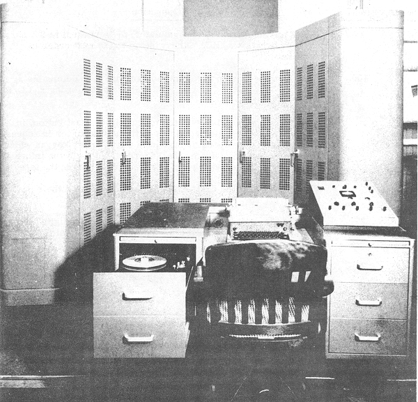
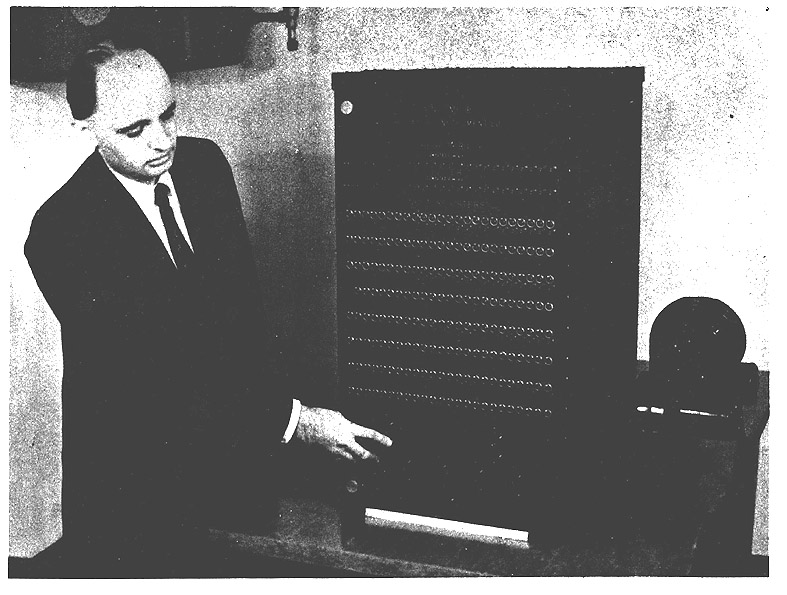
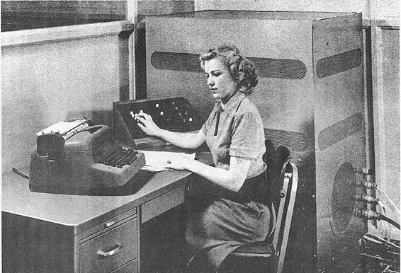
Figure 1 - JAINCOMP-B1, less program control unit
THE JAINCOMP-B1 COMPUTER
Donald H. Jacobs
The Jacobs Instrument Company
4817 Bethesda Ave.
Bethesda 14, Maryland
Although the JAINCOMP computers (Figure 1) are the simplest type of digital computers of which we have knowledge, we often have difficulty in explaining them to other people because of problems in semantics. The difficulty arises from the fact that they try to view our computers from the same point of view as they use with serial machines, and do not appreciate that our logical approach is, different and simpler. The confusion is compounded by our use of the same words that they use, but we mean different things by them. The serial computers all use crystal-controlled oscillators as "clocks" to synchronize the motion of pulses through the machines. We use no such component, as our computers are asynchronous. When their addition or transfer processes are considered, JAINCOMP computers can be viewed as having an infinitely high clocking rate, for all digits are manipulated simultaneously instead of in sequence (at a rate determined by a "clock") as in a serial machine.
For these reasons I am going to request those of you who know something of conventional serial computers to forget everything you know and let me start from scratch. You will see that our machines are different (being all-parallel all-electronic) from the conventional ones, and because of their differences they possess some extremely important major advantages.
The logical layout of JAINCOMP-B1 is shown in Figure 2. The heart of the machine is the arithmetic unit which contains three parallel-type registers, together with facilities for adding, shifting, and complementing. Inasmuch as any mathematical computation can be performed via these basic operations, all the actual computing in the machine is performed in this unit. The other parts of the computer control the flow of information into and out of this unit, and control the operation of this unit. The arithmetic unit adds two 24-digit numbers (JAINCOMP-BI being a 24-binary-digit machine) together in eight microseconds.
The arithmetic unit is caused to perform operations like subtraction, multiplication, or the taking of arc sires, via instructions received in the form of pulses from the subprogram units. These units, each consisting of a small group of subminiature tube circuits which issue sequences of order pulses, cause the various arithmetic operations to be performed in the sequence indicated by the program control unit. The use of a multitude of subcontrols greatly simplifies programming the computer, and also greatly reduces the amount of storage required for the solution of a given problem, as compared to the amount of storage which would be required by a serial computer to solve the same problem.
The storage unit of this computer has two sections for the following uses: (1) storage of intermediate results during a program and (2) storage of fixed constants which are changed from problem to problem.
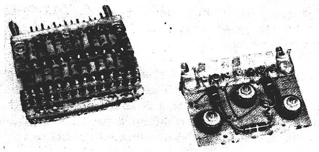
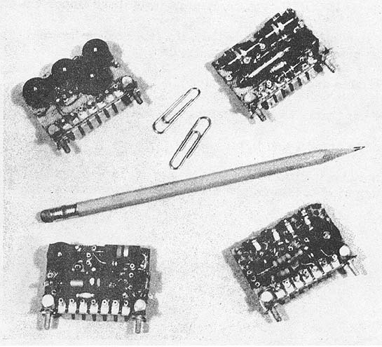
The intermediate results are stored statically in magnetic cores. This type of storage was first developed and employed by The Jacobs Instrument Company. Eight microseconds are required for the storage of-a 24-digit number in this storage, and the access (read-out) time is three to four microseconds for a 24-digit number. In JAINCOMP-B1, the magnetic cores (plus the associated gates) for three digits are mounted on a simple plug-in subassembly weighing less than one ounce. A new, faster, and much more compact version of this type. of storage, which has recently been developed, provides a 24-digit storage register, complete with gates, on a single plug-in subassembly weighing 2-3/4 ounces with all components, mounting boards, connectors, wiring, etc. Its size is 1-7/16 by 2-1/8 by 13/16 inch. The old and new versions of magnetic storage are shown in Figure 3.
Fixed constants, stored on punch cards or switches, are of the type which remain fixed through a given computation, but are changed from problem to problem. In JAINCOMP-B1 they are stored with switches; with other JAINCOMP computers punch cards are used. This punch-card type of storage is very compact and inexpensive; yet it provides an access time, for any 24-digit number in storage, of two microseconds. The punch cards are of course not read out electromechanically; rather are they read out electronically, and hence they can be read tremendously faster than punch cards used in conventional business machines. JAINCOMP-B1 has eight 24-digit switch registers of this general type.
Figure 2 - Block diagram of JAINCOMP-B1
Figure 3 - Magnetic storage registers: new 24-digit version of left, old 3-digit version on right
An important and distinguishing characteristic of JAINCOMP computers is that generally neither program instructions nor addresses are placed in storage. This makes it possible for JAINCOMP computers to use far less storage capacity than serial computers when solving the same problems. If it is desired to have a computer whose orders can be modified, JAINCOMP computers can be wired to permit this type of operation.
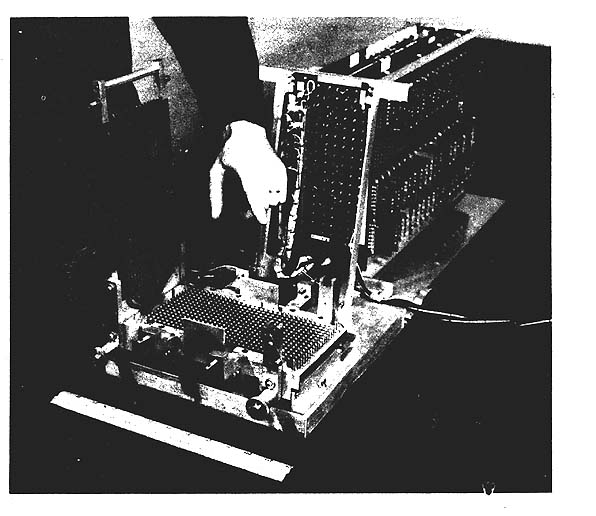
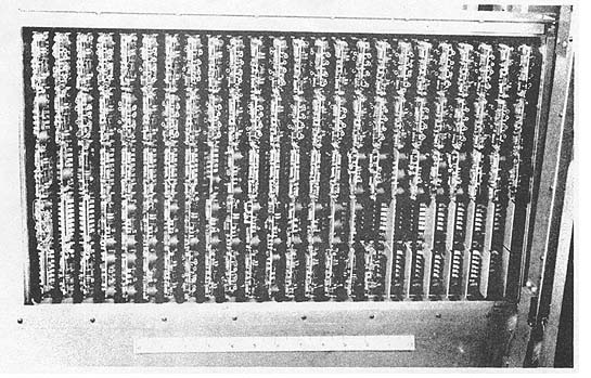
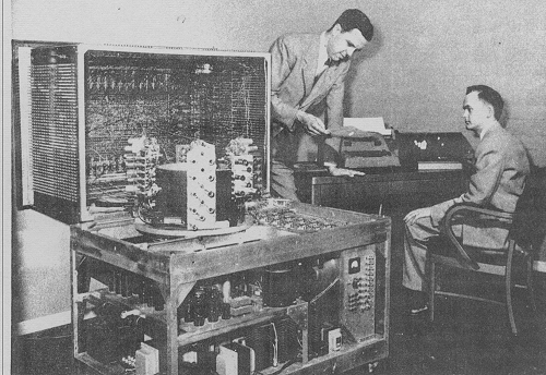
The program control unit (Figure 4) is controlled by a punch card divided into a number of vertical columns, each column comprising 16 punch positions. In the first column are punched holes to indicate the first group of computing operations to be performed. Up to five operations can be initiated simultaneously with holes punched in a single column. The instructions for successive steps can be set up with holes punched in successive columns. All hole positions are sensed simultaneously with metal fingers, and the columns are read in succession by an electronic sequencing system. The punched positions in each column are transformed into orders by a set of five decoding matrices, and are routed from them to the appropriate points. The program control unit permits conditional decisions, iteration processes, and various other operations to give the computer great flexibility. The punch-card holder could be replaced with a magnetic tape unit if it were desired to handle computing programs of unlimited length. This substitution could be made without changing the basic circuitry of the program control unit.

Figure 4 - Program control unit. Punched card holder open, showing spring-loaded fingers
Because of the unique programming method used in JAINCOMP-B1, and because up to five operations can be initiated simultaneously, programs of appreciable length can be set up in very few computing steps. For example the following equation can be solved in a total of 15 computing steps:
It is important to note that the preparation of a program to-solve a problem is extremely simple, and can be performed by an unskilled individual after a few hours of instruction. A large team of mathematicians to code a problem for this machine is decidedly unnecessary. This feature makes possible the use of a JAINCOMP machine in any laboratory. In this connection it is pointed out that, in 1948, Dr. Howard Aiken of Harvard staffed, "...if-all the computing machines under construction were to be completed, there would not be staff enough to operate them." This statement pretty well indicates a basic limitation on the serial computing technique. The value of a machine that can be operated without a skilled staff is quite evident. The development of such a machine is believed to be a very important step forward toward broadening the fields of application of digital computers.
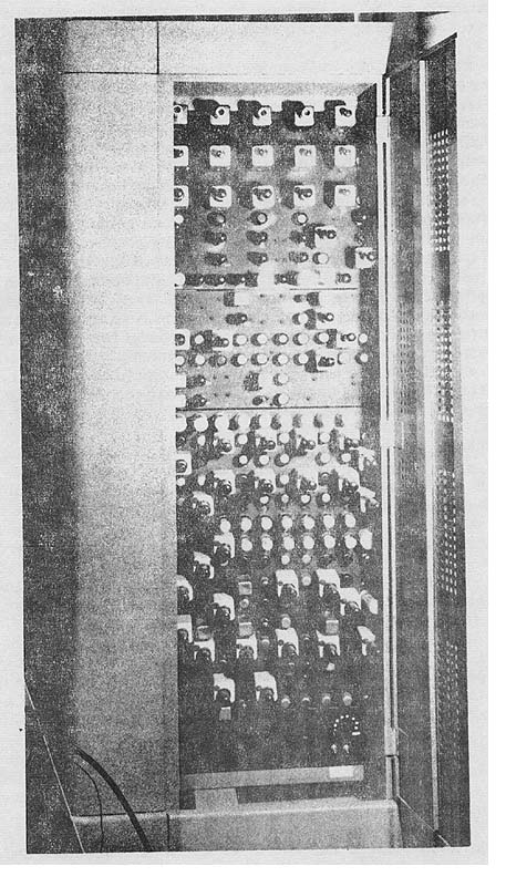
JAINCOMP computers employ newly developed circuits of unusual reliability. These circuits are all mounted on small plug-in boards, and any circuit can be replaced in less than 30 seconds. Four typical circuits are shown in Figure 5. The heaviest complete circuit, with all components, mounting board, and connections, weighs 1-1/2 ounces. The stability of these circuits results in a new standard of reliability for digital computers. Many of these plug-in circuits are being marketed individually. All plug-in subassemblies are mounted on panels which can be swung out (Figure 8) for easy access.
The type of logic employed with the JAINCOMP computers causes them to be very small. JAINCOMP-B1 occupies a space 18-1/2 by 21-1/4 by 30 inches, exclusive of the recently added punch-card program control unit, and weighs 110 pounds. It contains 300 subminiature tubes.
The JAINCOMP-B1 computer has very simple input and output systems; special input and output devices must be added when the computer is adapted to a specific use. These computers can be used for conventional computing purposes, and complex classified problems are being run on JAINCOMP-B1. Because of their very high speeds, and their ability to accept inputs from instruments and to control instruments with their outputs, they can also be used for real-time control or simulation.
When used for computation, these computers can accommodate multichannel inputs from magnetic or paper tape, keyboards, electric typewriters, etc. Output devices for computational use can consist of high-speed mechanical or oscilloscope recorders, magnetic tape, electric typewriters, etc., depending on requirements.
When employed for real-time control or simulation applications, JAINCOMP computers can accept inputs from measuring and detecting devices of numerous sorts, and the computer outputs can control motors, valves, indicators, etc. The computers can perform complex calculations on the inter-relationships of the inputs, and use the results of these computations to control the various outputs. Numerous inputs and output can be accommodated.
The Jacobs Instrument Company has developed various sensing and measuring devices for measuring various physical quantities and feeding them to the computer, and it has developed devices for controlling other apparatus with the computer's output.

Figure 5 -Four representative subassembliesUpper left - Multiple transformer unit Upper right - Bistable multivibrator. Lower left - Monostable multivibrator Lower right - Three-usec delay line plus auxiliary circuits

Figure 6 - Typical panel swung out for access,containing plug-in subassemblies To sum up, JAINCOMP-type computers have these important characteristics:
- have extremely high speed-they are fast enough for real-time control even when rapidly changing quantities are to be controlled,
- are reliable and easily maintained,
- can be programmed very easily by an average person,
- are very compact and light,
- need only very little magnetic storage because program, instructions, transfer orders, and computing constants are not placed in magnetic storage.
THE MONROBOT ELECTRONIC CALCULATORS
E. J. Quinby
Monroe Calculating Machine Company
555 Mitchell Street
Orange, New JerseyINTRODUCTION
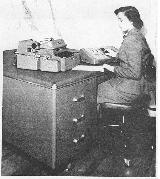
The MONROBOT III Electronic Calculator (Figure 1) is a general-purpose sequence-controlled calculator having 20 decimal-digit capacity with decimal fixed centrally between the tenth and eleventh digits. Any problem that can be solved by numerical methods can be programmed for solution by this calculator. Computation is automatic and results are printed by a high-speed electric typing machine.

Figure 1 - MONROBOT III electronic calculator
The most important single feature of the MONROBOT is its simplicity. Since both numbers and commands utilize the familiar decimal system there is no need for training an operator in binary arithmetic. Since the machine handles 20-digit numbers, the difficulties of scaling and overflow prevention are completely eliminated. Numbers and orders may be conveniently entered on an extremely simple keyboard and the calculator is controlled by means of only two push buttons and two selector dials. The calculator commands are inserted as the algebraic statement of the problem to be solved. Even a novice finds it possible to program problems after the first day's acquaintance with the input keyboard.
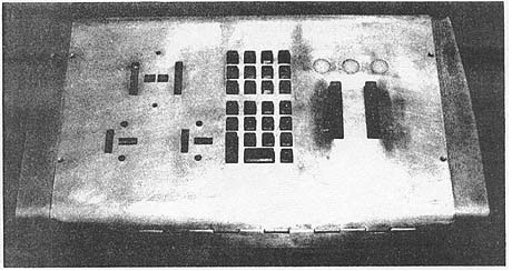
Figure 2 - Keyboard for MONROBOT III
Another important feature is economy in initial cost, maintenance, and space occupied (the top of a standard-sized metal office desk). Only 700 vacuum tubes and 200 diodes are employed throughout. STORAGE SYSTEM
The MONROBOT III has magnetic drum storage facilities which can record a maximum of 100 twenty-digit decimal numbers with algebraic sign, and 200 operational orders. Both orders and numbers remain undisturbed in storage unless they are deliberately erased or replaced. Such changes may be made via the keyboard, or occur automatically during a calculation process. Designation of Number Locations
The location of each number in storage is designated by a symbol called the number address. The symbols range from a0 through k9, using the ten alphabetic letters
a, b, c, d, e, f, g, h, j, k
(the letter i being omitted to avoid confusion with the numeral 1), and the ten decimal digits
0, 1, 2, 3, 4, 5, 6, 7, 8, 9.
The letters a, b, ... , k correspond to decimal digits so that the first ten storage locations are
a0, al, a2, . . . , a9,
the next ten are
b0, b1, b2, . . . , b9,
and so forth. Every number used in programming and calculation is assigned a number address, and no number can be used by the calculator until it has first been submitted to the storage unit.Designation of Order Locations
The location of each order is assigned a numerical symbol, called the order address. The symbols range from 00 to 99 inclusive. In general, orders are used sequentially, starting with the order in location 00 and progressing through the integers 01, 02, 03, etc. ORDERS - PROGRAMMING BASIC OPERATIONS
An order consists of five elements: four addresses, A, B, C, and D, and an operation, OP. The addresses specify number and order storage locations. The operation, OP, may be any one of eleven basic operations which the computer is capable of performing. These are: (1) addition (2) subtraction (3) multiplication (4) division (5) comparison (6) modification (7) print (8) print-stop (9) stop (10) read numbers (from perforated tape) (11) read orders (from perforated tape) Operations (5) and (6) (comparison, modification) are special operations that facilitate programming, and (7), (8), and (9) (print; print-stop, stop) are operations controlling the printing of results and termination of computation.
The elements of an order are arranged schematically as shown in Figure 3.
If OP is one of the operations (1) to (4) above, then A, B, C, and D are as shown in Figure 4. +---+---+---+---+----+ | A | B | C | D | OP | +---+---+---+---+----+ Figure 3
+---------+---------+--------+-------+-----------+
|    A    |    B    |    C   |   D   |    OP     |
+---------+---------+--------+-------+-----------+
| Operand | Operand | Result | Next  | Operation |
|         |         |        | Order |           |
+---------+---------+--------+-------+-----------+
               Figure 4
Addresses A and B .specify the locations of the two numbers involved in the operation, address C specifies the storage location to which the resulting sum, difference, product, or quotient is sent, and address D informs the calculator where it may find the next order. An example of an order of this type is shown in Figure 5.
Order 36 directs the calculator to add the contents of a2 and d3, and to place the result in storage at location e7; it then directs the calculator to continue to order 37. The order may be stated briefly as follows: add (a2) and (d3) and store the result in e7; then go to order 37. (In accordance with convention, parentheses are placed about a storage location to denote the contents of that location; thus (a0) is read, "the contents. of storage location a0.") In any order involving one of the arithmetic operations (1) to (4), the result of the operation may be delivered to the storage location of one of the operands; it then replaces the former contents of that location. +-------+----+----+----+-----+------+ | Order | A | B | C | D | OP | | No. | | | | | | +-------+----+----+----+-----+------+ | 36 | a2 | d3 | e7 | 37 | + | +-------+----+----+----+-----+------+ Figure 5
The comparison order provides for conditional transfer of control so that the machine will perform iterative routines until convergence is reached, and will then start performing other operations. Modification is useful in conserving orders when the same operation or sequence of operations is to be performed on several different operands. If, for example, it is desired to print out 50 of the numbers in storage, only one print order and one modify order are necessary. As each number is printed, the modify order automatically changes the address of the next number to be printed so that 50 distinct printing commands are not required.. ABSOLUTE MAGNITUDES
In each of the orders the arithmetic operation is normally carried out with consideration of algebraic sign. However, it is possible within the same operational command, to specify that the operation be performed using the absolute magnitude of either one or both operands, A and B, and/or that the absolute magnitude of the result be placed in storage at address C (the comparison order being excepted in the latter case). In an, order of this type, the operation symbol is supplemented by the corresponding addresses A, B, or C.
Addition, subtraction, comparison, and modification are performed at a rate of 450 operations per minute, including access time, while multiplication and division are performed at a rate of 100 operations per minute. Printing proceeds at a rate of 10 characters per second. Facilities are provided for dropping unwanted digits so that printing time may be minimized.
This description applies to the MONROBOT furnished to the Cambridge Air Force Research Center, which includes facilities for perforating paper tape. For special applications, additional storage capacity may be "plugged in." PROBLEMS FOR WHICH THE MONROBOT IS SUITED
The MONROBOT is a general-purpose calculator, and hence suited to any problem within its storage capacity. Because of the simplicity of its keyboard it is particularly efficient when employed to accept data directly, performing calculations immediately upon receipt of each number entered. A typical application of this type is wind tunnel data-reduction, where calculations may be performed immediately following the entry of force and moment readings. Larger and more expensive calculators are not practical for such work because the user cannot justify the idle time during keyboard entry of numbers.
A partial list of problems which can be conveniently processed on the MONROBOT includes root finding, matrix inversion, integration, differencing and interpolation, and trigonometric functions.

Figure 1 - CADAC, typewriter, and operator control panel
THE CADAC R. E. Sprague
Computer Research Corporation
3348 West E1 Segundo Blvd.
Hawthorne, CaliforniaINTRODUCTION
The CADAC is a general purpose or universal computer representing the culmination of efforts to apply new techniques in the design of digital computers. They have produced a highly reliable, efficiently small, moderately priced computer in a field which has been noted for highly unreliable, extremely large, very expensive computers.
In this paper I shall discuss the general characteristics of the CADAC, touch briefly on the design methods which were treated in another paper, present figures on its performance, and briefly describe the latest improvements in its input-output equipment. GENERAL CHARACTERISTICS
The CADAC is a Turing-type machine with numbers and commands stored in the same form in the memory which can store 1024 42-binary-digit words. It uses the three-address system and has the full complement of commands; add, subtract, multiply, divide, compare, extract, shift, print, tape write, and halt.
The memory is a magnetic drum rotating at 40 rps giving an average access time of 12.5 milliseconds. For the three-address commands involving four excess times, the average time for multiplication or division is 90 milliseconds and for all other commands about 55 milliseconds.
By use of minimum access programming, on the average .of two of the four access times can be cut to zero reducing the above times to 65 and 30 milliseconds each.
Figure 2 - Close-up view of CADAC control panelThe binary number system is used for internal operations and the octal system is used for filling and printing. The initial input-output equipment has been a keyboard and standard automatic typewriter (Figures 1, 2, and 3). A manual magnetic tape unit was originally planned for the computer which would receive output information from the machine automatically, but be used manually for input. Circuitry for the tape output command was included in the machine, but the tape unit was abandoned in favor of a superior unit.

Figure 3 - CADAC in open position
The CADAC is completely contained in a portable cabinet, 2-1/4 feet wide by 3-1/2 feet long by 4-1/2 feet high (Figures 1 and 2). The control and arithmetic portions are located on a hinged hollow top (Figures 3 and 4) which covers the drum memory. All three sections rest on top of the power supply chassis which occupies half the volume and makes up 4/5 of the 500-pound weight of the computer (Figure 3).
There are 31 flip-flops in the computing section and 70 drivers, making a total 101 tubes around the top periphery of the unit (Figure 4). Four plug-in boards contain 2,500 crystal diodes in this unit (Figures 4 and 5). The memory contains 16 main channels and 5 other channels, including 3 operating registers (Figure 6). There are 62 tubes used for recording and playback. The remaining 32 tubes of the 195 total are in the power supply. The computer draws 40 amps at 110 v including the memory motor and ventilating blower.
Figure 4 - CADAC computing center, outside view
Figure 5 - CADAC computing center, inside viewDESIGN METHODS
The techniques used in the design of the control and arithmetic units of the CADAC have been described in a paper presented at the Wayne University Meeting of the Association for Computing Machinery. Briefly, symbolic logic is used to arrive at combinations of standard circuits to perform all the operations required. The block diagram is replaced by a time flow diagram and a set of symbolic logical equations which completely define the arithmetic and control units. These two units are actually intermingled into one called the computing center. The memory design is no different from most magnetic-drum designs which use the non-return-to-zero recording system.
Figure 6 - CADAC magnetic-drum memory
The design methods result in reliable, nonintermittent-type failure operation. They also reduce the number of vacuum tubes appreciably while still not using a very large number of diodes. PERFORMANCE OF THE CADAC
The computer was tested in California over a five-month period, beginning in August 1951. It was shipped by plane in December to M.I.T. where it was evaluated by the staff of Whirlwind and put into operation two weeks after shipment. Following the evaluation, it was moved to another location at M.I.T. and placed in reliable operation in one day. I mention the transportation because in comparing reliability of performance of general-purpose computers, moving them has had rather dire effects in the past.
The machine was placed in final operating condition approximately January 15th. With the exception of one two-week period, the computer had been operated as of February 16th over the one month which elapsed on the average of five days per week and four to five hours per day. A large portion of this operating time was devoted to maintenance training of an engineer and a technician. The problems were, therefore, to a large extent test problems so that failures were readily detectable. Over this one-month period, only one machine error occurred, giving an average time between errors of 25 operating hours. A preventive maintenance schedule has been followed so as to check all diodes and tubes and replace them before they reach design limits.
Because of the preventive maintenance schedule combined with the long periods between machine errors, it is felt that the noninclusion of checking circuits in this computer was a justifiable design attitude. Checking circuits would add more components and make failures more likely. Checking of errors that do occur can be programmed in the CADAC as in any serial machine. IMPROVED MODEL OF CADAC
Computer Research Corporation has completed plans for an improved model, CADAC 102 A, which will have better input-output equipment and several engineering design changes of an internal nature.
A block search magnetic-tape auxiliary memory of 100,000 words will replace the semiautomatic tape unit. Two tape commands will allow reading and writing on the tape with automatic searching for tape addresses.
A Flexo-Writer unit with punched paper tape facilities will be used for filling and printing. Filling may be manual from ,the keys or automatic from the tape. Printing and tape punching may take place simultaneously. Standard tapes may be prepared while also filling the computer or on remotely located Flexo-Writer units.
The input-output number system will be changed to facilitate filling and printing of decimal information. The octal system can still be used for filling and printing if desired. When decimal numbers are to be filled, the decimal digits are. entered in groups of four pulses. The computer is then programmed using the subroutine method to convert these numbers to binary equivalents. The reverse procedure is used for printing.
Several engineering design changes have been made in the memory and computing center which will not affect the use of the machine with one exception. An inspection has been included which will cause the computer to halt and an indicator light to go on if a number is taken from the memory instead of a command. This will, in effect, provide some automatic checking and will take care of certain programming errors. The other changes are being made to facilitate production of the computer.
A production run of the CADAC 102 A is being planned and because of recent additions to Computer Research Corporation's production facilities, the machine is now available at a new low price and on short delivery.


Go to On Line Documents, Go to Go to Antique Computer home page
Figure 1 - Elecom 100 computer and control desk
THE ELECOM 100 Albert Auerbach
Electronic Computer Corporation
265 Butler Street
Brooklyn 17, New York
The Elecom 100 computer (Figure 1) was built in answer to the requirement for a low cost, small, relatively simple machine with, nevertheless, sufficient flexibility for general scientific application. The machine was constructed in a 3-1/2-month period, and test began on March 15. Results thus far have been quite promising, demonstrating that the basic engineering design is sound. GENERAL DESCRIPTION
The Elecom 100 is a serial, binary machine operating at a basic pulse rate of 115 kcs. It utilizes a 10-inch magnetic drum rotating at 3600 rpm as a "high-speed" memory, and a 1200 foot reel of 1/2-inch magnetic tape as auxiliary memory. Data (numbers and/or instructions) are handled in groups of 30 binary digits, defined as a word, and a 1/8 inch track or channel on the drum provides for 64 such words at a pulse density of 60 per inch. Eight such channels comprise the 512 word internal memory. Three additional tracks are used as address and timing channels. Since extreme speed was a secondary factor in the computer design, relay selection of the. memory channels is utilized.
Tape data is read or recorded in blocks of 64 words (i.e., the contents of one drum channel) at a pulse density of 75 per inch. The tape data is recorded in 3 parallel channels, a fourth channel providing sprocket or timing pulses. Between data blocks on the tape a space is provided for starting and stopping time; the data block and space occupy about 10 inches. The total tape capacity is thus 1440 blocks, or roughly 92,000 words. The tape moves at 7.5 inches per second, corresponding to a speed of about 50 words per second. Before use, the tape is processed by a separate unit called a "sprocketer" whose function is to examine the tape and to lay down sprocket pulses only in acceptable areas.
The input-output facilities also include an electric typewriter which serves to initially prepare program and data tapes, enter words directly into the memory, and print out intermediate and final data as directed by the computer. Input printing is a single word at a time. Provisions are made for preceding a word with a particular three-octal-digit address for direct insertion into the given memory position. It is also possible to automatically type into sequential addresses, starting from any desired address in the memory. For output printing, manual insertion of an appropriate type-out order permits printing the contents of any desired address and, of course, this can also be done automatically under machine control. Further, a manual control is provided for printing out from an address or instruction count register.
Data may be entered or printed in either the octal or bioctal system, in which groups of three binary digits, or two such groups, are treated as single characters. The octal and bioctal digits correspond from 0 to 7, but bioctal 8 is represented as octal 10, bioctal 9 as octal 11.,: Both the octal and bioctal combinations are formed by striking single keys; labeled 0 through 9, the type of insertion being controlled by a function switch. The bioctal representation thus permits direct decimal insertion of data. Additional bioctal combinations are interpreted by the computer as typewriter carriage return, space, and dash; these characters are needed for output "editing." To make use of decimal data requires a conversion by the machine itself between decimal and binary systems which is accomplished by an appropriate conversion routine stored on the tape and called for as required. It is possible, incidentally, to handle alphabetic data bioctally, using the 64 possible combinations of two-octal digits. To the present machine it would be necessary to add only a more extensive decoding table and additional solenoid actuators for the typewriter keys. Programming for the machine would then be arranged to avoid arithmetic operations on alphabetic data. This addition is intended in future models at some increased cost.
Coding or programming for the computer is basically three-address. An instruction consists of ten octal characters. For internal or arithmetic instructions, the first octal digit designates the operation, the remaining nine digits designate three addresses (each a group of three digits). In the case of tape input-output instructions, the first digit again denotes the operation; the second digit is a memory channel, which is followed by two additional instruction digits. Numeric data is also a group of ten octal digits or an equivalent five bioctal digit group. The computer handles this data in straight binary fashion, with the binary point considered as being between the first and second octal digits as normally written. The most significant binary digit represents the sign, the next two binary digits represent the numbers 0 through 3. Negative numbers are thus represented in complement form with respect to binary 8. ORDER CODE
The actual instructions performed by the computer are shown in Table 1 together with corresponding instruction times. In computing these times, we have allowed for operation of a read-write relay, for relay switching of channels, and for the average latency period. A 3-ms switching interval has been used (actually 2 milliseconds should be adequate). Minimum latency coding should cut these times by at least a third.
The internal instructions are coded in simple three-address form. In the ADD instruction, (4) (A1)(A2)(A3) indicates that the contents of address A1 and A2 are to be added algebraically, and the result transferred to A3. The SUBTRACT instruction (5) is similar, the contents of A1 being algebraically subtracted from A2, the result going to A3. On the HIGH-ORDER MULTIPLICATION instruction (2) the numbers in addresses A1 and A2 are algebraically multiplied, and all but the 27 least significant bits are stored in A3. If an overflow (beyond ± 4) occurs in the (2), (4), or (5) orders, an indication is sent to the control panel and the machine halts. LOW-ORDER MULTIPLICATION (1) multiplies the numbers in A1 and A2, retaining only the 27 least significant binary digits. The two most significant digits in the low order product are zero and the sign is always positive. The result again goes to A3. By combined use of the high and low order multiplications "multiple" or "double" precision multiplication is obviously possible. Using the (3) order we can obtain the high order product (as with the (2)) but the product has been "rounded" off in the usual way. In the (6) or LOGICAL MULTIPLICATION order, the numbers in A1 and A2 are multiplied digit by corresponding digit, the result being stored in A3. It may be noted that the (6) instruction is essentially an extraction operation, permitting the selection of digits in, say, A1, by proper choice of the 1's in A2. In the BRANCH or (7) order, the number in A1 is examined. If A1 is negative and not zero, the next instruction in the program sequence (i.e., the normal sequence) is called for. If A1 is zero, the next instruction is taken from address A2. If A1 is positive, we proceed to A3. Completing the set of internal orders is a HALT. The machine interprets all zeros in such a manner as to stop, retaining all data, presenting a visual indication different from that appearing when an overflow stops the machine.
TABLE 1
Order Code
The external (tape and typewriter) instructions are indicated by a zero in the first (most significant) octal digit, and distinguished from a HALT by additional digits in the third and fourth octal positions. The second octal digit defines one of the eight memory channels to or from which a block of 64 words is to be transferred. The next three digits (A2) are not significant. The last three digits in the A3 position are significant only in typewriter instructions. Thus in the TAPE READ order ((0(n) 42) we read from the magnetic tape a particular block and record this data on the nth channel. The (0(n) 43. conversely reads channel (n) to the tape. In both cases, one-to-one correspondence between tape and drum positions is maintained. The (0) 46 order simply moves the tape backward one block at a time without reading or recording. The second octal digit in this case is not significant. The typewriter instructions are designated by the last two groups: ((0)(n) 03 - A3) and ((0)(n) 13 - A3). In both cases, address A3 in channel (n) is typed out--03 providing normal octal typeout, 13 giving bioctal or decimal typeout-which also permits output editing. FUNCTIONAL DESCRIPTION
The basic machine cycle is divided into four steps referred to as KO to K3. On KO the address of the instruction being called from the memory (held in the Address Register) is fed to Time and Channel Selector circuits (Figure 2). Channel selection is accomplished by relay switching which takes on the order of a millisecond. We therefore must wait for relay closure before actual selection of one of the 64 words around the drum. For this reason you will note the channel selector inhibition on the Time Selector. The timer input t0. the Time Selector specifies successively the 64 drum locations which are compared to the count in the Address Register. Upon coincidence, the memory switch is activated and the selected word in the already selected channel is transferred to the Order Register through a Read-Write Control,, set, on the KO cycle, to Read. This essentially completes K0, the actual transfer; by definition, occurring as the first or J step of K1 (defined as JK1).
On JK1 the count in the Address Register is increased by one. At the end of this cycle, the instruction, now in the Order Register, sets up the Decoder, thus supplying the control signals required to execute the given instruction. In the case of the three-address internal instructions, the A1 address is now sent from the Order Register to the Time and Channel Selectors. During the remainder of K1, we wait for the A1 coincidence which occurs as described above. Upon coincidence, K1 is completed, and on the first or J step of K2, the specified word is transferred from the memory. In the arithmetic and external instructions, this transfer is always to the Accumulator. During JK2 the word is immediately acted upon in accordance with the signals supplied by the Decoder. In the BRANCH instruction, however, the word is sent to circuits within the Address Register where its value and sign are examined.
Figure 3 - Elecom 100 with cabinet door open
On K2 proper, address A2 is chosen as above, the A2 portion of the instruction (still in the Order Register) going to the Channel and Time Selectors. On JK3, the word in this A2 address is read from the Memory, again to the Accumulator, and acted upon under control of the Decoder as before. K3 proper is the interval during which the A3 address is chosen, and on JK0 we read our result from the Accumulator, through the Read-Write Control (now set to Write), to the specified address.
The above sequence is of course modified as required by the instruction being executed. For example, in a BRANCH instruction immediately after the examination of the word in A1 ; i.e. on K2; the A2 address in the Order Register (or A3, if the word in A1 is positive) is transferred to the Address Register. In this case the machine recycles to K0. On HIGH ORDER MULTIPLICATION on JK3, A1 is transferred from A to R (where it acts as the multiplier), while A2 simultaneously enters A. A second cycle is added to JK3 during which A2 is transferred to L where it becomes the multiplicand. In the course of these transfers, the signs of the "ier" and "icand" are examined and the product sign determined and stored. Negative numbers are complemented in passing through A, so that both the numbers in R and L are known to be positive. Negative products are recomplemented before being stored in the memory on JK0, The K3 cycle is extended further for this particular order to permit 29 shifts. Except for certain variations introduced by the location of the binary point between the 27th and 28th digits, the conventional scheme of successively examining each of the digits in R (starting with the least significant) and adding the icand to the shifted partial product for each 1 in R is employed. The 30th shift terminates the repetitive steps. R incidentally acts as its own shift counter. A pulse has been introduced into the sign position, known to be blank since R is necessarily positive. This pulse is sensed to terminate the multiplication and permit transfer of the product to A3 on the JK0 cycle.
The normal machine cycle is further modified during the tape input-output operations. In this case, 64 words are to be transferred to or from the drum. Transfers occur by way of A and a synchronizer which matches machine speeds to the asynchronous tape, utilizing the magnetic tape sprocket channel in this process. (The transfers again occur during an extended K3 cycle.) A unit adder in the Order Register counts the 64 words entering or leaving the Memory. In output typing, the Print Control counter performs the synchronization, counting down the 60-rps drum speed by means of a 7-stage counter. The third stage of the counter sets a typing speed of 7.5 characters per second. The second and third stages together also define a repeating sequence which first clears flip flops holding the digit to be printed; then permits setting these flip flops, first for bioctal, and then octal, characters; and finally activates thyratrons which control solenoids on the keyboard. The remaining counter stages are used to count ten characters, after which the operation is terminated by stepping from K3 to K0. The digit-by-digit word read out to the data flip flops is controlled by R (which is used as a precessor). The words are held in L during this operation, having been transferred to L from A.
With regard to the circuitry employed in the computer, extensive use is made of single-tube modulator-type flip flops, pulse transformers, and highly compact delay lines of up to 100-usec delay for register storage. Gates and buffers are cascaded with considerable saving in tubes.
The flip-flops are packaged and plug in, as do the transformers and crystals (which are arranged in clusters of up to eight crystals per cluster). The machine contains 240 tubes, roughly 2000 crystals, and takes about 3kW from the power line. It stands in a rack cabinet about 10 feet wide, 6 feet high, and 2 feet deep: Standard rack construction (Figure 3) is used and components are widely separated to avoid ventilation problems. The drum is housed in a separate unit. The remaining unit is the control desk, which holds the typewriter, tape unit, and control panel.