A GE-225 is found
(The first machine I was paid to play with ;-))
Table of Contents
|
Background
Images and comments about: On-Line Documents |
|
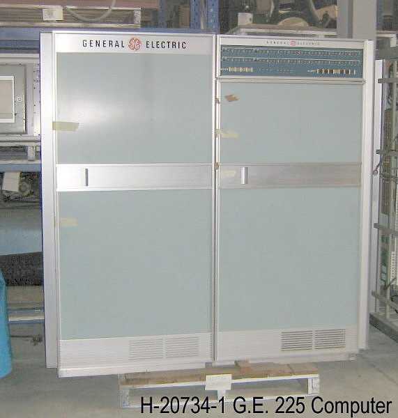
The General Electric 225 (introduced about 1960) was the first digital computer that I
was paid to work on (or play with depending on your view point.) One's first computer
is a bit like one's first love or dog ;-)) Here are some tales of
that adventure.
For about 8 years I have kept my eyes open for General Electric "Computer Department" computing equipment. Lurking about the Computer History Museum in Mountain View, California helps keep one focused and is a center of activity. The first computer manufactured by the "Department" was the "ERMA" under contract to Bank of America. The initial tube design of a fixed program machine was made by SRI (now Stanford Research Incorporated) and "modified" "by the good folks at G.E." (an advertising slogan at the time) into a transistorized general purpose computer. (It did have one very special instruction - the "tumble instruction" designed to help sorting. It had 3 or 4 operands and could well be an example of a "complex" as opposed to "RISC" instruction.) One of the original 30 machines is on display at Bank of America's private museum in Concord, CA. The next was a contract to manufacture (and provide support for) the NCR 304. Nothing further was located by anyone that I know of for five years, and several General Electric "Computer Department" reunions. |
One is found, 2006, w permissions
|
On July 6th, 2006, Peter Volk - Assistant Collection Manager
of the Queensland Museum
(South Brisbane, Australia, phone +61 (0)7 3840 7555) e-mailed me
saying that there was a GE-225 in good condition in that institution.
He asked if I could verify the identification of various components,
and sent images of that machine.
Image permissions
|
|
Peter Volk here, from Queensland Museum.
Yes, the GE225 is still sound and safe in our collection. The 2011 floods didn�t come anywhere near it, and it has been well housed and secured. Is it for sale or exchange? In practical terms, probably not. It was the first digital computer in Queensland and is considered a significant part of the state�s history as a consequence. We value it more for that association than we do for its technical significance, though that is, in itself, considerable. We would need to be offered a really significant sum to consider parting with it, or be offered an object that had equal significance to Queensland history. If you wish to make a formal inquiry about the possibility of purchase or exchange, you should contact our museums C.E.O. Dr Suzanne Miller [e-mail address deleted] , who would forward the inquiry to staff for proper assessment and report before she replied. That report would probably require us, in turn, to contract with an accredited valuer of such objects to give us a ballpark dollar value, which would require us, first, to find such a person. The whole process between initial inquiry and final response could take a few months. The Queensland Museum is a government funded and operated museum, and is charged by Act of Parliament to collect and preserve material of significance to the history of Queensland. This means that, even if the financial offer was very, very attractive we may find ourselves unable to ethically or legally accept it. That is an assessment that would be made at a paypoint considerably above my own. If you wish to make such an inquiry I�m happy to give you what advice I can. I�m still quite grateful to you for the context and history info you provided me on the GE225�s a few years ago. Sincerely
Peter Volk
PO Box 3300 | South Brisbane BC | Queensland 4101 | Australia
|
Unit History
From Queensland Museum Record Sheet - Historical Database H-20734-1
Planning for a large computer for Brisbane began in 1957. The G.E.225 was installed at the university in 1962, the first large
computer in Old. Last operated 16 February 1977. Data specifications received with donation.
From lecture given by Wilber Williams on "History of I.T. at Old Uni" in 2002.:
The last job on the G.E. was run by Prof. Sydney Prentice on the 16/2/1977, between 16:25 and 16:30. The job card is
preserved at the University. The computer was purchased in 1962 for 148,000 pound, plus 8000 pound to aircondition the
building. The original and primary purpose of the computer was to help calculate transformer designs. The GE was replaced
as the University's major machine areound 1968 by a DEC PDP 10, for the sum of $620,000.00, but the GE remained in use
until 1977. The DEC itself was decommissioned in 1984. (It is rumoured that the reason the GE remained in use so long was
that the University payroll system was kept on it, and nobody wanted to risk a migration.) - P. Volk 16/6/2003
Denis Bainbridge writes
AGE was Australian General Electric. We were the Australian sales and support office for GE Computer Dpt.Phoenix AZ.
The University of Queensland was the first 225 system sold in Australia.
The Bank of NSW was the next customer with a 225 and two sorters. Later adding a 235 with another sorter. A photo of
this site attached. Only thing left from these computers is CPU console.panel and a memory core stack.
Cheers
Denis Bainbridge
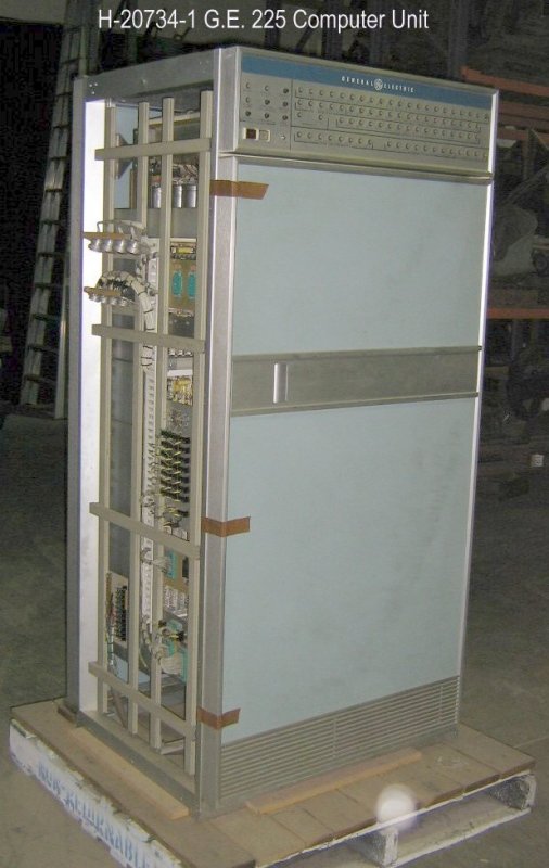
The lower panel with the electric outlets is normally hidden by the desk/table.
The round brown plug on the left is for the card reader -
I don't know what is going on on the right. A guess would be the electric typewriter.
The typewiter didn't fail very often ;-))
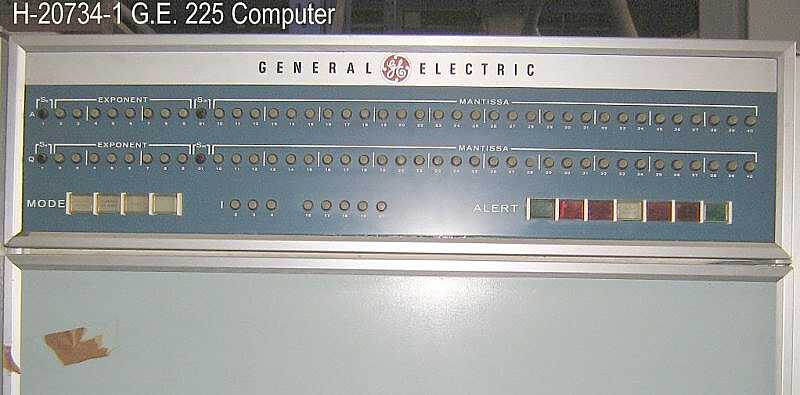
Images Copyright of the Queensland Museum. Used by permission.
You may note the fields on the display panel marked
"Exponent" and "Mantissa"
which is not technically correct if viewed as logarithms,
but are what computer folks call the parts of a
floating point operand. :-))
As a point of reference, to send a floating point value to/from this unit took over 66 microseconds to fetch the
load/store command from memory and fetch/store the operands to/from memory. The 20 bit wide data transmission over the
cable overlapped the memory operations.
Images Copyright of the Queensland Museum. Used by permission.
Those long light colored arms that could swing down on
top of the tape in the reel were called "tape packing arms".
These attempted to keep the tape from wrinkling between
layers as the large torque motors (not seen) started
and stopped the reels as fast as practical. I think it was a desperate attempt to
"do something, anything".
Tape "cinching" - wrinkling between layers - was a real
and largely unsolved problem with these drives -
IBM F.E.s also talked of the problem with their drives :-((
Images Copyright of the Queensland Museum. Used by permission.
Any error, like out of paper signal,
and you lost the print line that you started to print
(it disappeared into thin air from the core print buffer). - Just plane mean! -
On the top image, the fifth light down from the top, the one you can barely
see under the white one, was the blue fatal error light.
If you ran out of paper, it went on, and you were dead,
you lost that line of print. Long story -
Many of the logic cards in this unit supported a printer formatting function, similar to the
IBM 1401. A template could be specified which controlled leading zero suppression (blanking),
dollar protection (for check writing, leading zeros or blanks have dollar signs inserted.
Unfortunately, most programmers, FORTRAN, and COBOL did not support this feature,
which was largely unused and unappreciated. If the same care had been applied to real world worries ...
It had a little electromagnetic clutch in the back side
that controlled paper movement - that sometimes developed an
annoying squeak - one beginning F.E. fixed that by putting
some oil in it - not a good thing, the clutch couldn't grab
to move the paper. - There was a toothed index wheel that sensed
when the sprocket feed went one line, so bad things didn't
happen, just that printing went from say 15 lines/second to
maybe one or two lines per second :-|
The bottom part is hammer driver cards and the brown thing
is the power supply for the hammers.
Images Copyright of the Queensland Museum. Used by permission.
I had forgotten, the model number of this machine, Peter responded with
So this machine seems to be an IBM 523, and this image may just be the best of an IBM 523 on the web.
In any case, the IBM 523 was extremely reliable - the most trouble free
peripheral (by far) in the GE 225 system. The GE instructors basically said -
"This 523 works well. We have shown you the GE drive circuits for the
punch magnets and clutches, and this is the big grey ugly 'shoe connector' to the machine,
that is all you need to know. OH yes, don't forget the 80-80 plug panel!"
Images Copyright of the Queensland Museum. Used by permission.
And Cables (hopefully under the raised floor :-)) and floor frames
Lots of twisted pairs to conduct lots of signals with a limited
amount of noise and cross talk.
These were the standard interconnects between the processor and
major peripherals such as printer controller,
magnetic tape controller, auxiliary arithmetic unit,
disk file controller, DataNet 15 (a serial interface controller,
like for TTY modems, and I forget what else)
Yes, one of the few G.E. peripheral things that worked well.
Transmission parity was checked, and the things just worked :-))
Images Copyright of the Queensland Museum. Used by permission.
And the Infamous Elliott Card Reader
For a less polite discussion of this little devil, click here.
The little grey assembly with yellow and red wires is likely the array of
12 lights to send light through card holes to an array of 12 photosensors
below the moving card. For some reason this assembly was removed from
it's place just before the top feed roll? The 12 volts lights were not driven hard (maybe 9 volts)
and "never" failed. Hole sensing was almost the only thing on this machine that worked
reasonably well.
In any case, the upper part is the input hopper,
not visible in the seemingly 2.5 pound cast iron block
with handle that pressed the cards down against the
bottom plate that - oh - you don't want to know -
Also wrapped about the input hopper is the connecting cable.
In any case, the metal gadgetry nearest you is the exit of
the cards into the output hopper discussed (or cussed) below.
That funny little gray finger thing is several layers of
feeler gage stock, maybe 0.002 inch thick,
whose purpose is to push the cards flying out of this
machine into the output hopper in an orderly fashion.
Just above the shim stock is a little adjustment screw
that you diddled to try to get the cards to go correctly
into the output hopper, with out:
It was easy to despise this machine. What a pile of poop!
This card reader was, I feel, one of the
main reasons that the only customer that re-ordered
General Electric Computer Department equipment was
the U.S. Army (Huntsville) - and they were using mostly paper tape
in their Saturn data logging application.
The G.E. marketeers and salesmen, to this day, refuse to admit that
an almost zero re-order rate had anything to do with the failure of the
G.E. Computer Department. They just smile and blather on about financing machines.
Dear Friends - there should be a special place in Hell for
who ever designed this part of the nightmare card reader.
To get cards out of this hopper, the operator pulled on the
little handle on the other side. As the operator pulled this
little tray out, the triangle thing you see would be pulled out
to 90 degrees from its present position, and try to catch the
cards falling down into this output hopper, making a temporary
bottom to the hopper while the output drawer was pulled out.
When the operator pushed the drawer in again, this temporary bottom
would disappear, permitting the cards that had dropped on the top
of this little flap to fall to the bottom of the drawer.
If the above is confusing and weird - you are correct.
Horrible things could happen until you got the knack of it.
You were well advised to stop the computer while
you removed cards from the Elliott !!!
Images Copyright of the Queensland Museum. Used by permission.
Yes - it worked :-)) Enough to give you an inferiority complex. If a unit was designed
or made by G.E. Computer Department, you had a lot of trouble with it. If it was made
by someone else (except the Elliott card reader!!) it worked better.
A fun quirk - the typewriter was fed by the "N" register.
To set up the N register to type a character, you arranged the
bits backward from the normal representation in the GE-225,
You set bit 0 into N register bit 5, bit 1 into N register bit 4, ...
You just shook your head and accepted the quirkyness :-| Like you can't fight city hall - and I live in California -
Somehow, the world blunders on -
Images Copyright of the Queensland Museum. Used by permission.
Images Copyright of the Queensland Museum. Used by permission.
Circuit Cards
Sizes of significant computing have decreased from - small room (UNIVAC 1950), several refrigerators (1960),
1 refrigerator (1970), desk top (1980), ... with each 10 years yielding more than 10x faster speed and 10x increased memory
and 5x decrease in price.
For comments, e-mail Ed Thelen ed@ed-thelen.org
History, Use & Ownership:
Hi Ed
Auxilary Arithmetic Unit - AAU,
.jpg)
H-20734-2 G.E. 225 Computer - Data Processor (2).jpg
the left side of the front frame of the 225
.jpg)
H-20734-2 G.E. 225 Computer - Data Processor (3).jpg
.jpg)
H-20734-2 G.E. 225 Computer - Data Processor (4).jpg
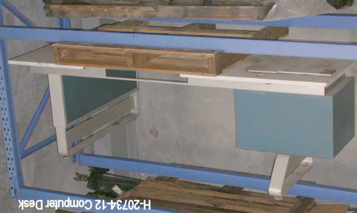
H-20734-12-ComputerDesk.jpg
The
Auxiliary Arithmetic Unit
of a GE 225 system.
It provided a 40 bit floating point
add, subtract, multiply and divide
at a much higher speed than if
done by software in the GE 225 computer itself.
.jpg)
Open doors - general construction - The little black plug with the little black screw handle at the lower right
of the right frame is a terminating plug for the data transmission cable used to read/write data and commands to/from
the AAU.
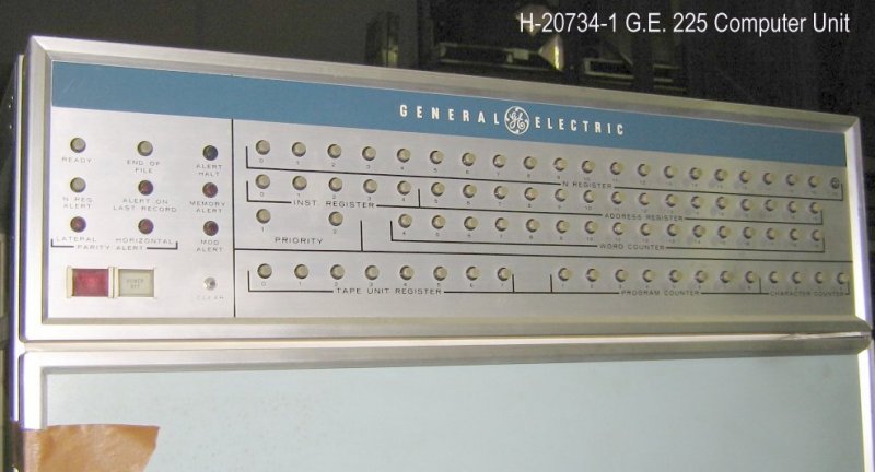
H-20734-1 G.E. 225 Computer Unit - control panel.jpg
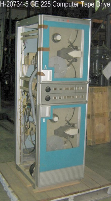
H-20734-5 GE 225 Computer Tape Drive.jpg
This one was a second generation, with "pucker pockets"
that grey unit that looks like a grey fish eating a white fish
This unit was like the long columns in say an IBM 729,
but much more limited buffering capacity and
a slot to a vacuum cleaner motor that created a lot
of "white" (no particular frequency) noise - horrible.
And the vacuum cleaner motors weren't very quiet either. For my own sanity,
I bought some long vacuum cleaner hoses, and placed the vacuum cleaner motors
under the raised floor.
.jpg)
.jpg)
H-20734-3 G.E. 225 Computer - Printer Control (2).jpg
.jpg)
.jpg)
H-20734-13 G.E. 225 Computer - Printer Unit (3).jpg
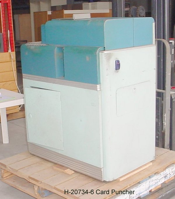
H-20734-6 Card Puncher.jpg
The GE system pictures show other vapour-ware card punches,
but this is what we had in service in the early 1960s
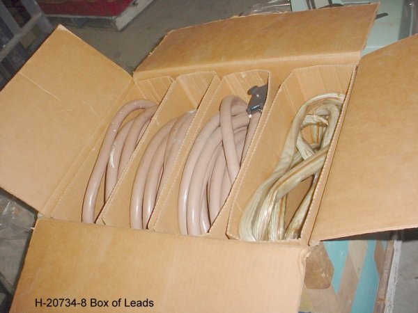
H-20734-8 Box of Leads.jpg
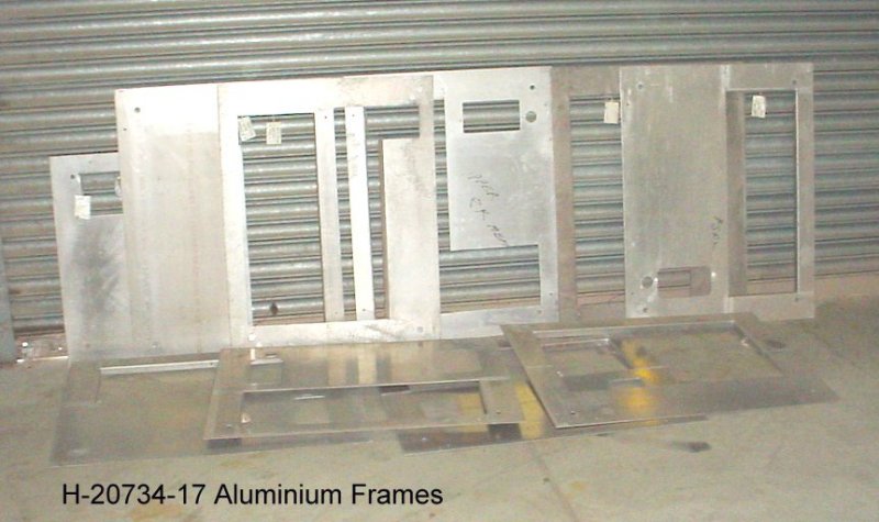
H-20734-17 Aluminium Frames.jpg
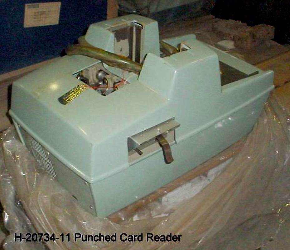
H-20734-11 Punched Card Reader.jpg
F.E.s and operators diddled this screw so much that
the little threads failed - and more robust nuts and screws
were substituted.
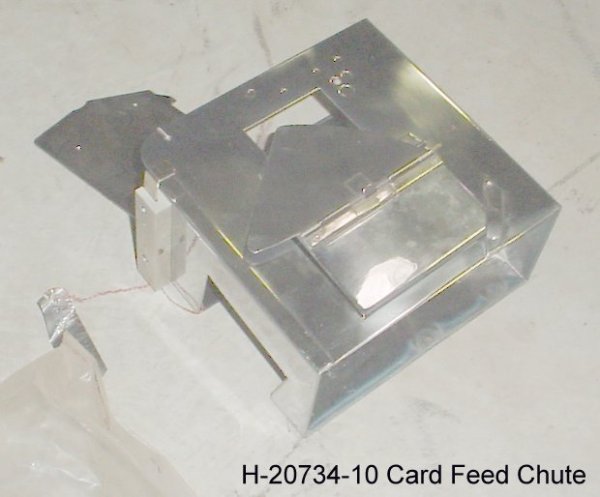
H-20734-10 Card Feed Chute.jpg
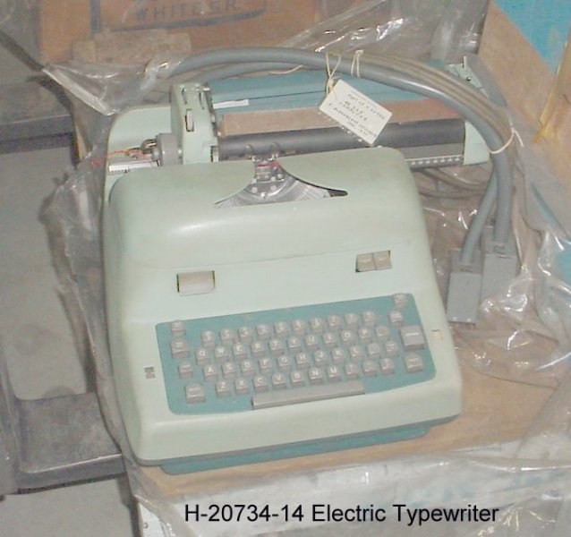
H-20734-14 Electric Typewriter.jpg
.jpg)
.jpg)
H-20734-18 G.E. 225 Computer - Paper Tape System (3).jpg
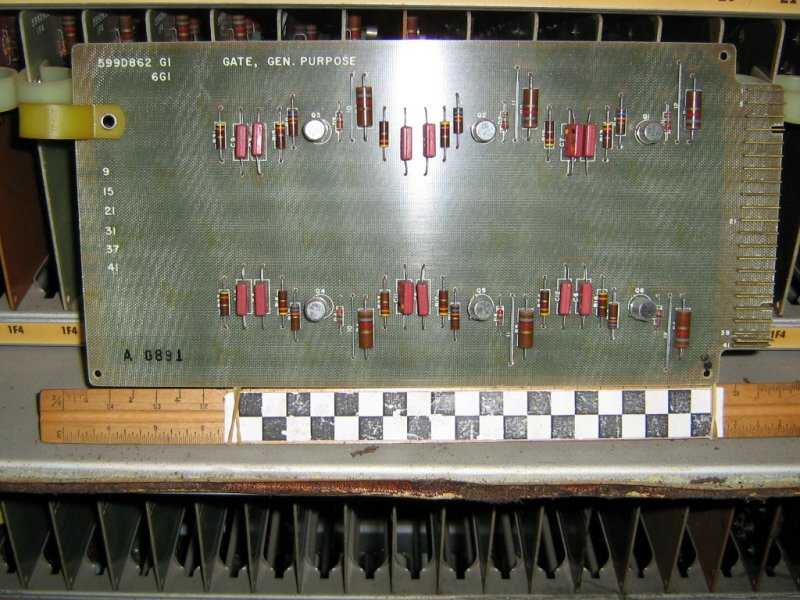
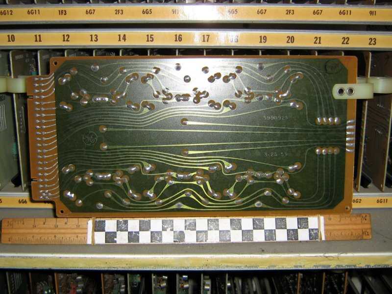
The circuit cards to the left (also called "boards") are the technology of about 1960. Each little round can houses one transistor.
The right hand side is the "bottom" side.
The density of discrete components per square inch increased each year as manufacturing technology permitted.
Images Copyright of the Queensland Museum. Used by permission.