Return to LGP-30

LGP-30 Supplement -

Goal: Extra techie information about LGP-30 machines
contains:


1st 2 sections of the above LGP-30 Maintenance Manual from Christian Corti

OCRed then translated by GOOGLE Translator then HTMLed to something like the German format and corrected the OCR some more
Part I
=======

Introduction
----------

The purpose of the instruction manual

This instruction manual is the basis of the technical Instruction for the electronic computing machines LGP-30 (Royal Precision Electronic Computer,) manufactured by Librasaope, Inc., Glendale, Calif.. Edited. Descriptive information Explanations on the theory of the functioning and the operating and Maintenance manuals for this facility are here in sufficient Dargelgt detail to allow qualified personnel, the full operation and maintenance.

The purpose of the facility

The LGP-30 is an all-electronic digital computer of spatial dimensions smaller than a conventional desk. The computing speed and memory capacity, with a lot of larger and more costly plants vergeleichbar. The basic unit can operate relatively ungeschultem staff. The Calculator was developed to provide scientific and technical Calculations a reliable and efficient small computer on the market.

General indicator

The LGP-30 is a programmgesteuerter all-purpose digital computer, a variety of mathematical and technical tasks solves. The Commands (encoded in digital form) and the numbers that which to work, are kept in a storage whose Contents could change.

The basic skills, commands or numbers with each other ver equal and command sequences change to be able to enable the Computer plant accordingly:

Part I, page 2

mathematical and logical operations on command or Figures in accordance with command sequences in the Memory, run;

two command sequences depending on the outcome a comparison between two figures or Befehlenauszuwählen;

one or more commands in accordance with a fixed Command sequence to change.

The computing system works internally in the dual system, but may encrypted decimal alphabetic characters and processed. It is working with a fixed point. All figures are treated as if the comma between the sign and the point with the greatest importance. All figures are between +1 and -1. (negative numbers are represented by complementation) Basic unit of information in LGP-30 called a word. Since it is a programmatic machine, a word either a number or a command and is internally by Dual 32 points. If a word is used to manufacturing data to store, the first bit the sign , 30 bits the size of the number and the last bit is for technical Space reasons.

The LGP-30 uses a Einadress command code, each command consists of three parts:

  • the command d.h. the numerical code for the operation, be executed. (4 dual posts),
  • the address d.h. the number of the space, during the execution of a warrant will be selected (12 dual points)
  • reserve bits, for the storage of constants or for specific calculations can be used (13 dual posts).

Part I Page 3

Since the machine as a one addresses computer works, the Address of the next command not to be separately . The commands are always in the order, in them. the drum stored until this order by jumping command, which is the address of the next command to be indicating is interrupted.

A magnetic drum with read-write heads and electronic Circles serves as an information storage of the computing system. This "Main memory" has a capacity of 4069 '! Locate. 64 tracks side by side in an axial direction contain 64 words on the Trommelumfazig .. Each track has its own reading write head. Of three time track with the same impetus contents are read, in conjunction with electronic circuits control functions and the choice of word and point positions on the Drum volume. Every single word of memory can be done by the track and the cell (situation on the Drum volume, 1 of 64) on. For the convenience of Programmer are the addresses of the word positions with two certain numbers from 00-00 to 63-63 to open. The berfi `t ~-irur.g such a designated address in the coordinates of Sour and cell is electronically.

In the command below list will be made in summary The form of computer automatically feasible operations. There are various terms register taken as the so-called Current memory are realized, a short access time to Registers. Each consists of a write head with one or more (drum rotation sense) following reading heads. The time lag between the writing and reading one bit in Current memory is one word. The read at this time Information is the write head back to the same Information is a word length puts back on the drum writes. The functions of the various circulation memory are as follows: The Befehlszählregister - contains the address of the memory cell, in the next command is executed.

Part I Page 4

The command register - it will just run the command noted. In addition, during the Multiplication or division temporarily disrupt the Operanten second.
The accumulator - he takes in the usual way one Operanten and stores the result of an operation., usually with word length.

Declaration of commands.

(m means that memory cell, which in address part of the command word means.)
B m Remove the battery and write the contents of the memory cell m into it.
A m Add to the content of the contents of the accumulator Memory cell m and keep the result in the accumulator.
S m Subtract the contents of the contents of the accumulator Memory cell m and keep the result in the accumulator.
M m Multiply the contents of the accumulator with the content the memory cell m and keep the more significant (upper) Half of the accumulator.
As N m M, but keep the less significant (lower) half in the accumulator.
D m Dividiere the contents of the accumulator by the content the memory cell m and keep the dual offices at 30 rounded ratio accumulator.
E m image of the logical product of the contents of the accumulator and the memory cell m, d.h. make the dual of the Accumulator in the places to zero, where in memory m also zeros. The remaining dual accumulator remain unchanged. This command is often used to some parts of words hide.
H m Write the contents of the accumulator in the memory cell m and keep the word in the accumulator.
As H C m, but then delete the accumulator.
U m Take the next command from the memory cell m. At the same time the command counter to this value, he one from there on, so that the next commands. the cells are taken to the cell m.
T m Take the next command only from the memory cell m, if the contents of the accumulator is negative, otherwise go normal.
Y m Write the address part of the word in the accumulator , in the address part of the word in memory m. Mostly is the word in memory m, a command whose address in this way has been adapted. The word in Accumulator remains unchanged.
R m joining a "1" to the number in command counters, which Address the next command and bring added indicating the new number in the address part of the word, in memory m. The address of the word in m is now 2 larger than the address of the memory cell, in which R is the command. Mostly follows the R-command Command to jump start a sub-programme. The R-command writes the address on his übernächste Address in the initial jump command of the sub-programme so that the command sequence wirder to the right place the main program returns.
I m an address reference is unnecessary. (m = 0000) The command brings the computing machine in a state in which he, Tape or keypad for her groups of bits in the Accumulator can. At every keystroke, a four-or sextet of her in the right Accumulator, while the existing content to 4 and 6 digits. left. After 8 Tetraden the entire accumulator filled. In tape input will automatically strip so long advance and every symbol in a Tetrade the accumulator over until a special stop command (usually after 8 Tetraden), but not compatible with the Z-command is the same. This means that the computer the following command.
P m Write an icon on the typewriter. The tracking part by m specifies which symbol to be written. It in this way can all 50 features the Sohreibma machine are triggered. If desired, simultaneously with a transcript of the tape time.
Z m machine continue. If m = 0000, it will necessarily be halted. If m = 0400, 0800, 1600 or 3200 or a combination these figures, the stop command ignored if the relevant, with 4; S, 16 and 32 marked NOT STOP button on the control panel is pressed.


Part II
=======

Technical description.
------------------------

The LGP-30 is an independent, self unit. All Elements from which the computers are in a single housing accommodated. The casing is made of steel and Alluminium with a hinged hood, ventilation openings and detachable Side parts. The device is mounted on wheels, at any desired To make change.

The main components of the LGP-30 are shown in Figure 1 and in the following sections.

The energy supply

The following tensions created equal:

+ 150 V, + 300 V, and - 160 V.

All tensions are by magnetic voltage regulated to constant output voltage. The Voltage fluctuations in the same Netzwechselapannungen 180 to 240 V. Each chassis has a current limit and therefore automatically protects against overloads and Short circuits. This is effected by AEG-voltage, their mode of action in the section on maintenance tasks.

An additional -20 VDC, which is necessary for a proper function of the computer is connected to a resistance generated in the return of the negative DC circle 0 V against potential.

The resistance is located at the front of the power supply.

Heating and separating transformers

All tubes are two special transformers heated. One of them feeds the tubes in the storage unit, the other the Tubes for the logical functions. The Transformatören T1 and T29, shown in Figure 1, have two primary windings, either the full or half the filaments of the tubes to deliver can. The tension for these transformers are also by a magnetic voltage (500 W) regulated, (Bil-3 below left).

Part II, page 2

A transformer for the electric typewriter, because you have your own network has Rectifier, whose Output from the computer her grounded.

Memory unit

The storage unit is divided into three separate units:

the storage drum with read-write heads and drive motor,
the head-selection diode matrix and
the card slots with the tubes.

These parts are shown in Figure 1 dargestllt. The storage drum is from a high strength aluminum alloy, is dynamically balanced and with quiet special camps.

A special cycle lane with 2048 bits in the drum eingefräst extent, a basic clock of about 130 kHz. On the drum surface is a 30 x strong Eisenoxydschicht under a special procedure raised.

Vierundsechzig read / write heads of the main memory are limited to six axial arranged strips attached, which on the one Half of the drum volume.

The normal distance between the head and drum surface is 20-25 u.

A two-word circulating memory and a special two-word circulating memory are located between the main memory capita strips and Right end plate of the drum holder. Three tracks are as a time track with the same content, which each Drum rotation in 64 different time-words. The Reading heads are associated with the main memory heads mounted. All heads are for the isolation and to increase the encapsulated mechanical stability, low windings and Sintered ferrite cores.

Part II, page 3

The drum is a belt by an asynchronous motor (250 W, 2800 rpm at 50 Hz) driven. The translation is so chosen that the drum with about 3900 rpm and the resulting umläuft Clock frequency 130 kHz.

The diode matrix for the head selection is on the outside of the left Trommelendplatte attached. Diodes for 128 head of the main selection memory on this plate. When choosing a certain ten head covered by these diodes writing or reading the signals Head added. The flexible leads the heads are on the back Matrix side of the plate angelötet, while a cable with the connectors Matrix with the amplifier Einschüben. The board memory unit contains Trommelt except:

21 cards with printed circuit
connectors for the signal lines, power supply and
the lead plates for cold air,
the cooling air power from the wärmeerzeugenden parts of the slots.

This storage unit on cards with printed circuit:

8 reading flip-flops
8 matrix driver
3 write amplifier
1 read / write gate, and
1 stroke generator.

Calculator and tail, (logic)

The computing and tail is divided into two parts aufgeteiltt

The diode network, called the logic board,
and below arranged
the cards with printed circuit board.
The logic board consists of two single plates, which sided with printed Switching system. Approximately 700 diodes are at the top the plate in columns, from 1 to 60 are numbered, and in 12 rows, each with two letters from A to Z means.

Part II, page 4

Between the anode and cathode of the diode are electrical connections in the form of printed lines.

All resistors and capacitors are at the bottom of the Logic plate. The diodes are working at voltages from 0 V or -20 V, and only these tensions are on the top of the logic board. Normally, the whole covered by a Leitblech what the Cold air over the diodes leads to heat resulting in adverse Working conditions due. Below the logic board are Printed circuit cards, which are:

5 triple flip-flop cards
2 inverter cards
1 and Kathodenfolger
3 Thyratron cards.

With the exception of reading signals from the main memory, the timing signals, of typewriters signals and signals from the control buttons lead Logikplatte.über all entrances to these cards.

To transfer the resulting heat is an air stream through Leitbleche wärmeabgebenden of the parts.

Control panel and cathode-ray tube

The proposed Kontrollampen keys and serve the following purposes:

  1. When you press the button "A", the device is switched on.

  2. When you press the button "off" the device is switched off.

  3. When pressed "pause" button is pressed, the DC abeschaltet and filaments reduced by half.

  4. If the key "operation" is depressed, get the tube their full heating and after about 50 seconds, the DC automatically switched on.

    If the keys "operation" and "input manually pressed, before the device is switched on, the self - States of "pause" to "holding" process.

    Part II, page 5

  5. The yellow light of the key "operation" indicates, the heating daB is in progress, and the drum starts.

  6. If the DC is switched on, the light goes off the key "operation" and the green light on the button "Ready" indicates that the device is ready to computing.

  7. With the keys "normal", "single operation" and "entering by hand," läBt is one of three possible operating conditions. In the "normal" by a starting signal commands the program automatically saved to a programmiertne Maintenance. In the case of "individual operations' • is to der'Rechenanlage a start signal an operation and then paused, A second signal is issued the next operation. . When entering by hand, the machine is ready, numbers or Commands from the typewriter to her and the accumulator to save. These three types of switches are against locked to prevent numbers or commands in memory by improper operation can be lost.

  8. When you press the button "Start" is a stored program in the Mode "normal" or "single operation".

  9. When you press the button "counter delete", the command register to zero.

  10. Pressing the button "command" means the transport of Contents of the accumulator in the command register if the Mode "single operation" or "by hand".

  11. If the button is pressed command, the Execution of the warrant register standing warrant.

    Part II, page 6

  12. A programmed stop will be overlooked if one or more Buttons with the inscription "No stop" button.
  13. If the "6-bit command button is pressed, all Dual six points each character of the typewriter in the Input into the accumulator. However, if this button not pressed, only four dual posts.
  14. When you press the button "jump" to forcefully to a jump possible execution of a suitable test encrypted command.
Depending on the operating condition each of the lights are in operation Buttons. Only one button, `the lights up. When a button is not lit, so nothing happens, then if they still pressed.

The "Start" button is not lit at "command of hand". But if they pressed, the next word in the command register and the command of one meter by 1. The execution of each logical or arithmetic or operation of input or output command is the green light "Converts." If no command as a result of a programmed or logical or Haltes by the result of a calculation not proper operation is held, the computing machine in a frozen state, through a red light "maintenance" is displayed.

The oscilloscope, with the control panel is combined shows in binary form the content of the three circulation register with the sign imagine, the command flag and the address points. Those are on the screen marked the Oszillographenröhre. The adjustment Oszillographen for the buttons are located below the screen under the plastic sheet with the logo. Below the Be dienungspultes there is a cage, the high-.und Heizspan nungserzeugung for the cathode ray tube sets (Figure 1). In addition to the Cage are the cards for the horizontal and vertical n.

Part II, page 7

All tensions, input and output signals via cable with Plug in the device, at the front of the device is the electric clock.

Relay box

The relay box is located below desRechen and at the Leitwerkes Back of the computer system. The relays and associated groups, which Order specify the tension control, and the transformers, the low voltage for the Kontrollampen in operating console supply, are housed in the chassis. Like all other Recheanlge assembly, this chassis with cables and connectors . With the exception of the Port for the input and output, the top of the left side of the machine, all Exchange tensions on this chassis.

The cooling

The case in which the computing machine is located, also contains the Body responsible for cooling the plant provides. At the front bottom left is a fan motor, which is a centrifugal blower to drives. There are about 1.2 m3/Min. Cold air with the help of Leitblechen wärmeerzeugenden on all parts. Through the openings in the Back of the case, the warm air hinausgeblasen, while the Fresh air by three air filter on the sides of the energy supply chassis and by mesh at the base of the machine applied. The angesaugte Air reaches delineated by the energy supply chassis into the blower.

The electric typewriter

An electric typewriter is the main inputs and gabevorrichtung of LGP-3Q. The typewriter has a hole streifenleser and Stanzer. If a tape is read, or if on the keypad of a typewriter key, means that the electric typewriter encrypted Signals through a cable to the computer systems as input information. In the same way signals from the computing device in the Typewriter, either as a sign printed, a corresponding ing tape produced or it is the tape reader .

Part II, page 8

The electric typewriter is on the code established by the Computing facility.

If the key 6-Biteingabe "is not pressed, only dual digits 1-4 scanned the channels. If the button is pressed, all Dual six digits, according to the hole combination imported. Although either 4 or 6 bits imported, should be given when you print Dual 6 digits of the computer writing machine, so that they can work properly. At a band to command or by a Command from the keypad can her information from the strip into the hole Machine can be entered. The appropriate type of Einlesens can Push of a button at the typewriter elected. It is a switch , to the typewriter by the computer to electric plant separated. You can tape-so produced, while the machine calculates. Figure 6 shows the layout of the buttons on the electric typewriter. For a convenient input and output is the typewriter with a special Switch for automatic equipped carriage return. The cars position, where the return should be done, you can manually set will. On the side of the typewriter are the paper tape puncher and the reader. The corresponding control keys are in Figure 6 . Entering a tape information corresponds to the input an information by hand. If the button "punching" is depressed, will be pressing any letter or number key the corresponding Learning hole combination in the hole punched Strip. The automatic Carriage return is not stamped. The paper tape reader can Squeezes ( the button "Start reading" set in motion or through the Reading relay through an input command. The reading of the Lochstreifens can by reading a "conditional stop" or by pressing the button "Read-stop" be interrupted. If a tape off and gedoppel , it can be stopped at any "conditional stop" be overlooked by the key "Conditional Stop" button. When a character incorrectly punched , creates a pressing "delete characters" that every 6 holes punched, and hence a non-readable characters. The start button the typewriter has the same function we start button on the operation nungepult the computing system.

Part II, page 9

Table 1
-----------------

6-bit keys of the typewriter
-----------------------------

Numeric control commands hex signs
Paragraph
123456 123456 123456
1 Ll 000110 Bb 000101 (upper Type) To / | \ 000100
2 *2 001010 Yy 001001 (lower Type) To \ | / 001000
3 "3 001110 Rr 001101 Parbumschaltung 001100
4 [delta]4 010010 Ii 010001 carriage return 010000
5%5 010110 Dd 010101 backspace 010100
6 $6 011010 Nn 011001 Tab 011000
7 [Pi]7 011110 Mm 011101 Conditional Stop 100000
8 [Sigma]8 100010 Pp 100001 Read 000000
9 (9 100110 Ee 100101 space 000011
0)0 000010 Uu 101001 erasure 111111
10 Pf 101010 Tt 101101 sign:
11 Gg 101110 Hh 110001
12 ij 110010 cc = + 001011
13 Kk 110110 Aa 111001-- - 000111
14 Qq 111010 Ss 111101
15 Ww 111110 Zz 000001
Other buttons
123456
:; 001111
?/ 010011
]. 010111
[, 011011
Vv 011111
Oo 100011
Xx 100111
Note: The figures in the columns above refer to the corresponding Holes in paper tape. With "0" is no hole there, a "1" is a hole While the 4-bit scanning only the characters Positions 1 through 4 in the computing machine. All the characters are only 6 entered in the 6-bit input. With the exception of Tabulierungs - and Sign space takes no control signs in the machine. In reading Tabulierungs or the space will sign either 4 or 6 hits Depending on the position of the 6-bit command button read.


Helpful note from Christian Corti


On Mon, 28 Jul 2008, Ed Thelen wrote:
> I didn't see anything that looked like a  general block diagram.

We have one (somewhere) as a bitmap which Klemens drew many years ago. It 
is based on the block diagram found in one of the many LGP-30 brochures. I 
will supply it later as soon as we find the file.

> A lot to chew on, not sure I really want to get into it -
>      and a different language makes it even more interesting -
> Trying to wander about on that diode matrix board :-(

Try to understand the logic equations, then you will understand the diode 
board. After all, it's just plain DTL (Diode-Tube-Logic ;-))
Take for example the equations for the P3 flip-flop (the underscore will 
pre represented by a leading '/'), see page III-34:

P3'  = i P2 + P3*
/P3' = i /P2 + /P3*

These are RS-FFs, so the first term defines the SET input, the second the 
RESET input. 'i' is the output of a cathode follower with the following 
term:

i = F G /H /Q1 Q2 /Q3 /Q4 + S2 S3 /H /G [ Q1 + /Q2 + (Q3 + Q4) + /F ]
     {----} {------------}
     Ph. 4   Opcode 0100

So, 'i' is TRUE during the execution phase (phase 4) of the opcode 0100 
(INPUT), thus P2 gets shifted into P3 (as P1 gets shifted into P2 and so 
on). This is the shift part of the INPUT instruction (the accumulator is 
shifter 4 or 6 bits to the left), then the computer stops. The character 
from the reader/typewriter is accessible on the P[1-6]* signals, so when 
the computer is restarted by the reader the character is put into the P 
FFs (i.e. reader bit P3* is put into flip-flop P3).

>
> But I got the main contactor "ME2" to close, giving power to
>   the next stage of startup :-))
>  Is the "Trommel-Motor" the drum drive motor?

That's right; here's a short vocabulary:
Tor gate
Röhre tube
Trommel drum
Befehl instruction / command
Umdrehung revolution
Spur track
Zelle cell / sector
Sprung jump
Speicher memory
Verstärker amplifier
lesen to read
schreiben to write
Kopf head
Takt clock
Ablenkung deflection
Spannung voltage
Strom current
Schreibmaschine typewriter
Wartung maintenance
Schaltplan schematics
Bedienungspult console (the part with all the buttons)

> Never did find the power supply rectifier tubes (I presume)
>   nor the filter capacitors, nor any regulators (I presume)

We don't have any power supply schematics, but its function is quite 
simple. There are no tubes in there, it's fully solid-state. There are 
only transformers, chokes, MP caps, selenium recitfiers and filter caps. 
The voltages are regulated on the primary side of each output voltage with 
the aid of a magnetic constanter (is that the correct term?).
There's an additional constanter outside the power supply for the heater 
transformers (one for the CPU and one for the drum electronics).
It's located at the bottom center of the machine next to the power supply.
One thing to watch out for are the oil filled metal paper capacitors in 
this constanter which tend to get hot and leak/short due to their age. 
This is not fatal, but be prepared for a sudden shutoff or for a peculiar 
smell.
This all is based on the german power supply; I'm not sure if the american 
one is built the same way (do you have pictures of yours?). Even the 
german one got redesigned over the years (from 1958 to approximately 
1964). The older one can be seen here:
http://computermuseum-stuttgart.de/dev/lgp30_40/netzteil.html
An exploded view of a german LGP-30:
http://computermuseum-stuttgart.de/dev/lgp30_40/lgp30_deko.html


Christian

--------------------------------------------------
Universität Stuttgart
Zentrale Dienste der Informatik
Universitätsstraße 38
70569 Stuttgart

EMail: Christian.Corti@informatik.uni-stuttgart.de
Tel: (+49) 711 / 7816-234
--------------------------------------------------


1st 2 sections of the above LGP-30 Maintenance Manual

OCRed and somewhat corrected

Teil	I 
   
Einleitung
----------
Zweck des Unterweisungshandbuches
Dieses Unterweisungshandbuch ist als Grundlage der technischen 
Unterweisung für den elektronischen Rechenautomaten LGP-30
(Royal Precision Electronic Computer,)hergestellt von Librasaope, 
Inc., Glendale, Calif., herausgegeben. Beschreibende Angaben, 
Erklärungen zur Theorie der Arbeitsweise und die Bedienungs- und 
Wartungsanleitungen für diese Anlage sind hier in ausreichender 
Ausführlichkeit dargelgt, um qualifiziertem Personal zu ermöglichen, 
die Bedienung und die vollständige Wartung auszuführen.

Zweck der Anlage
Der LGP-30 ist ein elektronischer Allzweck-Digital-Rechner von 
geringeren räumlichen Abmessungen als ein normaler Schreibtisch. 
Die Rechengeschwindigkeit und die Speicherkapazität sind mit viel 
größeren und kostspieligeren Anlagen vergeleichbar. Die Grundeinheit 
kann von verhältnismäßig ungeschultem Personal bedient werden. Der 
Rechner wurde entwickelt, um für wissenschaftliche und technische 
Berechnungen einen zuverlässigen und leistungsfähigen Kleincomputer 
auf den Markt zu bringen.

Allgemeine Kennzeichen
Der LGP-30 ist ein programmgesteuerter Allzweck-Digital-Rechner, der 
eine Vielzahl von mathematischen und technischen Aufgaben löst. Die 
Befehle (verschlüsselt in numerischer Form) sowie die Zahlen, mit 
denen gearbeitet wird, sind in einem Speicher aufbewahrt, dessen 
Inhalt man verändern kann.

Die grundsätzlichen Fähigkeiten, Befehle oder Zahlen miteinander ver
gleichen und Befehlsfolgen verändern zu können, ermöglichen der 
Rechenanlage demgemäß:

Teil I Seite 2

rechnerische und logische Operationen auf Befehl oder 
Zahlen hin in Übereinstimmung mit Befehlsfolgen, die im 
Speicher enthalten sind, auszuführen;

zweierlei Befehlsfolgen in Abhängigkeit von dem Ergebnis 
eines Vergleiches zwischen zwei Zahlen oder Befehlenauszuwählen;

einen oder mehrere Befehle in Übereinstimmung mit einer festen 
Befehlsfolge zu verändern.

Die Rechenanlage arbeitet intern im Dualsystem, jedoch können 
verschlüsselte dezimale und alphabetische Zeichen verarbeitet werden. 
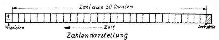
Es wird mit festem Komma gearbeitet. Alle Zahlen werden so behandelt, 
als ob das Komma zwischen dem Vorzeichen und der Ziffer mit dem 
größten Stellenwert steht. Alle Zahlen liegen zwischen +1 und -1. 
(negative Zahlen werden durch Komplementbildung dargestellt) Die 
Grundeinheit einer Information im LGP-30 nennt man ein Wort. Da es
sich um eine programmgesteuerte Maschine handelt, kann ein Wort 
entweder eine Zahl oder einen Befehl enthalten und wird intern durch
32 Dualstellen dargestellt. Wenn ein Wort nur benutzt wird, um zu 
verarbeitende Daten zu speichern,, gibt das erste Bit das Vorzeichen 
an, 30 Bits die Größe der Zahl und das letzte Bit wird aus technischen
 Gründen als Zwischenraum benötigt.

ggggggggggraphic


Der LGP-30 benützt einer Einadress-Befehls-Code, wobei jeder Befehl 
aus drei Teilen besteht:
dem Befehl, d.h. dem Zahlencode für die betreffende Operation, 
die ausgeführt werden soll.(4 Dualstellen),
der Adresse, d.h. der Nummer des Speicherplatzes, der 
während der Ausführung eines Befehls angewählt wird 
(12 Dualstellen),
den Reserve-Bits, die für die Speicherung von Konstanten 
oder für besondere Berechnungen verwendet werden können 
(13 Dualstellen).

Page 3


Da die Maschine als ein Ein-Adressen-Rechner arbeitet, ist die  
Adresse des nächsten auszuführenden Befehls nicht gesondert 
angegeben. Die Befehle werden immer in der Reihenfolge ausgeführt, 
in der sie auf. der Trommel gespeichert sind, bis diese Reihenfolge 
durch einen Sprungbefehl, welcher die Adresse des nächsten 
auszufuhrenden Befehls angibt, unterbrochen wird.

Eine Magnettrommel mit Lese-Schreibköpfen sowie elektronischen 
Kreisen dient als Informationsspeicher der Rechenanlage. Dieses 
"Hauptgedächtnis" hat eine Kapazität von 4069 '!orten. 64 Spuren 
in axialer Richtung nebeneinander enthalten je 64 Worte auf dem 
Trommelumfazig.. Jede Spur hat einen eigenen Leseschreibkopf. Von 
drei Zeitspuren mit gleichbleibendem Inhalt werden Impulse gelesen, 
die in Verbindung mit elektronischen Kreisen Steuerfunktionen 
übernehmen und die Auswahl von Wort-und Ziffer-Positionen auf dem 
Trommelumfang ermöglichen. Jedes einzelne Wort des Speichers
kann durch die betreffende Spur und die Zelle(Lage auf dem 
Trommelumfang, 1 von 64) angewählt werden. Zur Bequemlichkeit des 
Programmierers sind die Adressen der Wort-Positionen mit zwei 
bestimmten Zahlen von 00-00 an bis 63-63 durchgehend bezeichnet. Die 
t`berfi~-irur.g einer so bezeichneten Adresse in die Koordinaten von 
Sour und Zelle wird elektronisch ermöglicht.

In der unten stehenden Befehlsliste werden in zusammenfassender
Form die vom Rechner selbsttätig durchführbaren Operationen beschrieben. 
Dabei wird auf verschiedene Register bezug genommen, die als sog. 
Umlaufspeicher realisiert sind, um eine kurze Zugriffszeit zu den 
Registern zu ermöglichen. Jeder besteht aus einem Schreibkopf mit 
einem oder mehreren (im Trommeldrehsinn) nachfolgenden Leseköpfen.
Die Zeitspanne zwischen dem Beschreiben und dem Lesen eines Bits im 
Umlaufspeicher beträgt eine Wortzeit. Die in dieser Zeit gelesene 
Information wird dem Schreibkopf wieder zugeführt, der die gleiche 
Information um eine Wortlänge versetzt wieder auf die Trommel schreibt. 
Die Funktionen der verschiedenen Umlaufspeicher sind folgende:
Das Befehlszählregister - enthält jeweils die Adresse der Speicherzelle, 
in der der nächste auszuführende Befehl steht.

page 4

Das Befehlsregister - in ihm wird der gerade auszuführende Befehl 
festgehalten. Außerdem nimmt es während der 
Multiplikation oder Division zeitweilig den 
zweiten Operanten auf.

Der Akkumulator	- er nimmt in üblicher Weise den einen Operanten 
auf und speichert das Ergebnis einer Operation., 
normalerweise mit Wortlänge .

Erklärung der Befehle.
(m bedeutet diejenige Speicherzelle,die im Adressenteil des Befehls
wortes bezeichnet wird.)

B m	Lösche den Akkumulator und schreibe den Inhalt der Speicherzelle m hinein.

A m	Addiere zu dem Inhalt des Akkumulators den Inhalt der 
Speicherzelle m und behalte das Ergebnis im Akkumulator.

S m	Subtrahiere von dem Inhalt des Akkumulators den Inhalt der 
Speicherzelle m und behalte das Ergebnis im Akkumulator.

M m	Multipliziere den Inhalt des Akkumulators mit dem Inhalt 
der Speicherzelle m und behalte die bedeutsamere (obere) 
Hälfte im Akkumulator.

N m	Wie M, aber behalte die weniger bedeutsame (untere) Hälfte 
im Akkumulator.

D m	Dividiere den Inhalt des Akkumulators durch den Inhalt 
der Speicherzelle m und behalte den auf 30 Dualstellen 
abgerundeten Quotienten im Akkumulator.

E m	Bilde das logische Produkt aus dem Inhalt des Akkumulators 
und dem der Speicherzelle m, d.h. mache die Dualen des 
Akkumulators an den Stellen zu Null, an denen im Speicher
m auch Nullen stehen. Die restlichen Dualen des Akkumulators 
bleiben unverändert. Dieser Befehl wird oft benutzt, um 
gewisse Wortteile auszublenden.

H m	Schreibe den Inhalt des Akkumulators in die Speicherzelle 
m und behalte das Wort im Akkumulator.

C m	Wie H, aber lösche anschließend den Akkumulator.

U m	Nimm den nächsten Befehl aus der Speicherzelle m. Gleichzeitig 
wird der Befehlszähler auf diesen Wert gesetzt; er 
zählt von da aus weiter, so daß die nächsten Befehle aus. 
den Zellen genommen werden, die der Zelle m folgen.

T m	Nimm den nächsten Befehl nur dann aus der Speicherzelle m, 
wenn der Inhalt des Akkumulators negativ ist, sonst gehe 
normal weiter.

Y m	Schreibe den Adressen-teil des Wortes, das im Akkumulator 
steht, in den Adressenteil des Wortes im Speicher m. Meistens 
ist das Wort im Speicher m ein Befehl, dessen Adresse 
auf diese Weise umgeändert worden ist. Das Wort im 
Akkumulator bleibt unverändert.

R m	Füge eine "1" zu der Zahl im Befehlszähler, welcher die 
Adresse des nächsten Befehls angibt hinzu und bringe die 
neue Zahl in den Adressenteil des Wortes, das im Speicher 
m steht. Die Adresse des Wortes in m ist also jetzt um 
2 größer als die Adresse der Speicherzelle, in welcher 
der Befehl R steht. Meistens folgt auf den R-Befehl ein 
Sprungbefehl zum Beginn eines Unterprogramms. Der R-Befehl 
schreibt dann die zu seiner Adresse übernächste 
Adresse in den Ausgangssprungbefehl des Unterprogramms, 
so daß die Befehlsfolge wirder an die richtige Stelle 
des Hauptprogramms zurückkehrt.

I m	Eine Adressenangabe ist unnötig. (m = 0000) Der Befehl 
bringt den Rechenautomat in einen Zustand, in dem er vom 
Lochstreifen oder Tastenfeld her Gruppen von Bits in den 
Akkumulator übernehmen kann. Bei jedem Tastenanschlag wird 
eine Vierer- bzw. Sechsergruppe von rechts her in den 
Akkumulator übernommen, während der bisherige Inhalt um
4 bzw. 6 Stellen nach. links geschoben wird. Nach 8 Tetraden
 ist der gesamte Akkumulator gefüllt. Bei Lochstreifen-Eingabe
 wird der Streifen automatisch so lange 
weitertransportiert und bei jedem Symbol eine Tetrade in 
den Akkumulator übernommen, bis ein besonderer Haltbefehl 
(normalerweise nach 8 Tetraden) kommt, der aber 
nicht mit dem Z-Befehl identisch ist. Dieser bewirkt, 
daß der Rechner zum folgenden Befehl geht.


P m	Schreibe ein Symbol auf der Schreibmaschine. Der Spurteil 
von m gibt an, welches Symbol geschrieben werden soll. Es 
können auf diese Weise alle 50 Funktionen der Sohreibma 
schine ausgelöst werden. Falls gewünscht, kann gleichzeitig mit 
der Niederschrift ein Lochstreifen angefertigt werden.

Z m	Maschine anhalten. Ist m = 0000, dann wird unbedingt angehalten.
 Ist m = 0400; 0800; 1600 oder 3200 oder eine Kombination 
dieser Zahlen, so wird der Haltbefehl ignoriert, 
wenn die entsprechenden, mit 4; S; 16 und 32 gekennzeichneten 
Schalter KEIN HALT am Bedienungspult gedrückt sind.

Teil	II 
-------------
         Technische Beschreibung.
         ------------------------

Der LGP-30 ist eine unabhängige, in sich abgeschlossene Einheit. Alle 
Elemente, aus denen der Rechner besteht, sind in einem einzigen Gehäuse 
untergebracht. Das Gehäuse besteht aus Stahl und Alluminium 
mit einer aufklappbaren Haube, Ventilationsöffnungen und abnehmbaren 
Seitenteilen. Das Gerät ist auf Rollen montiert, um jeden gewünschten 
Platzwechsel vornehmen zu können.

Die Hauptbestandteile des LGP-30 sind in Bild 1 gezeigt und in den 
folgenden Abschnitten beschrieben.

Die Energieversorgung
---------------------
Es werden folgende Gleichspannungen erzeugt:

    + 150 V,        	+ 300 V,	und	- 160 V.

Alle Spannungen sind durch magnetische Spannungskonstanthalter 
geregelt, um konstante Ausgangsspannungen zu gewährleisten. Die 
Spannungskonstanthalter gleichen Schwankungen der Netzwechselapannungen 
zwischen 180 und 240 V aus. Jedes Unterchassis hat eine Strombegrenzung 
und schützt sich daher selbsttätig gegen Überlastungen und 
Kurzschlüsse. Dieses wird bewirkt durch AEG-Spannungskonstanthalter, 
deren Wirkungsweise in dem Abschnitt über Wartungsaufgaben beschrieben ist.

Eine zusätzliche -20 V Gleichspannung, die notwendig ist für eine 
ordnungsgemäße Funktion des Rechners, wird an einem Widerstand 
erzeugt, der in der Rückleitung des negativen Gleichstromkreises 
gegen 0 V potential liegt.

Der Widerstand befindet sich an der Vorderseite des Netzgerätes. 

Heiz- und Trenntransformatoren
------------------------------

Alle Röhren werden von zwei besonderen Transformatoren geheizt. 
Einer davon speist die Röhren in der Speichereinheit, der andere die 
Röhren für die logischen Funktionen. Die Transformatören T1 und T29, 
dargestellt in Bild 1, haben zwei Primärwicklungen, um entweder
die volle oder die halbe Heizspannung für die Röhren liefern zu 
können. Die Spannung für diese Transformatoren werden ebenfalls 
durch einen magnetischen Spannungskonstanthalter (500 W) geregelt, 
(Bil-3 unten links).


Teil II Seite 2

Ein Transformator ist für die elektrische Schreibmaschine vorgesehen, 
da sie einen eigenen Netzgleichrichter besitzt, dessen 
Ausgang vom Rechner her geerdet werden kann.

Speicher-Einheit
----------------
Die Speicher-Einheit ist in drei getrennte Einheiten aufgeteilt: 
    die Speichertrommel mit Lese-Schreibköpfen und Antriebsmotor,
    die Kopf-Auswahl-Dioden-Matrix und 
    die Karten-Einschübe mit den Röhren.

Diese Teile sind in Bild 1 dargestllt. Die Speichertrommel besteht 
aus einer Aluminiumlegierung hoher Festigkeit, ist dynamisch ausgewuchtet 
und mit geräuscharmen Speziallagern versehen.

Eine besondere Taktspur mit 2048 Bits ist in den Trommelumfang eingefräst, 
um einen Grundtakt von ca. 130 kHz zu erzeugen.
Auf die Trommeloberfläche ist eine 30 u starke Eisenoxydschicht 
nach einem Spezialverfahren aufgebracht.

Vierundsechzig Lese-Schreibköpfe des Hauptspeichers sind auf sechs 
axial angeordneten Leisten befestigt, die sich auf der einen 
Hälfte des Trommelumfangs befinden.

Der normale Abstand zwischen Kopf und Trommeloberfläche beträgt 
20-25 u.

Zwei Ein-Wort-Umlaufspeicher und ein besonderer Zwei-Wort-Umlauf-speicher 
befinden sich zwischen den Hauptspeicher-Kopfleisten und 
der rechten Endplatte der Trommelhalterung. Drei Spuren werden 
als Zeitspuren mit gleichbleibendem Inhalt verwendet, die jede 
Trommelumdrehung in 64 verschiedene Zeit-Worte aufteilen. Die 
zugehörigen Leseköpfe sind zusammen mit den Hauptspeicherköpfen 
montiert. Alle Köpfe sind zur Abschirmung und zur Vergrößerung der 
mechanischen Stabilität gekapselt, haben niederohmige Wicklungen und 
Kerne aus gesintertem Ferrit.

Teil II Seite 3

Die Trommel wird über einen Keilriemen von einem Asynchronmotor 
(250 W, 2800 U/min bei 50 Hz) angetrieben. Die Übersetzung ist so 
gewählt, daß die Trommel mit etwa 3900 U/min umläuft und die entstehende 
Taktfrequenz 130 kHz beträgt.

Die Dioden-Matrix zur Kopf-Auswahl ist an der Außenseite der linken 
Trommelendplatte befestigt. 128 Dioden zur Kopf-Auswahl des Haupt
speichers sind auf dieser Platte montiert. Bei Auswahl eines bestimm
ten Kopfes werden durch diese Dioden die Schreib- oder Lesesignale dem 
Kopf zugeführt. Die flexiblen Zuleitungen der Köpfe sind an der Rück
Seite der Matrixplatte angelötet, während ein Kabel mit Steckern die 
Matrix mit den Verstärker-Einschüben verbindet. Die Baugruppe "Speicher
einheit" enthält außer der Trommelt:
     21 Karten mit gedruckter Schaltung,
     die Steckverbindungen für Signalleitungen, Stromversorgung und 
     die Führungsbleche für die Kühlluft,
die den Kühlluftstrom über die wärmeerzeugenden Teile der Einschübe führen. 

Diese Speicher-Einheit enthält an Karten mit gedruckter Schaltung:
    8 Lese-Flip-Flops 
    8 Matrix-Treiber
    3 Schreibverstärker
    1 Lese-Schreib-Tor, und 
    1 Taktgenerator.


Rechenwerk und Leitwerk, (Logik)
---------------------------------
Das Rechen- und Leitwerk ist in zwei Teile aufgeteiltt
     das Diodennetzwerk, bezeichnet als Logikplatte, 
und darunter angeordnet
     die Karten mit gedruckter Schaltung.

Die Logikplatte besteht aus zwei Einzelplatten, die beiderseitig mit gedruckter 
Schaltung versehen sind. Etwa 700 Dioden sind auf der Oberseite 
der Platte in Spalten angeordnet, die von 1 bis 60 durchnummeriert sind, 
und in 12 Zeilen, von denen jede mit jeweils zwei Buchstaben von A bis Z 
bezeichnet ist.


Teil II Seite 4

Zwischen den Anoden bzw. Kathoden der Dioden bestehen elektrische Verbindungen 
in Form gedruckter Leitungen.

Alle Widerstände und Kondensatoren befinden sich auf der Unterseite der 
Logikplatte. Die Dioden arbeiten bei Spannungen von 0 V oder -20 V, und 
nur diese Spannungen sind auf der Oberseite der Logikplatte vorhanden. 
Normalerweise wird das ganze von einem Leitblech bedeckt, welches die 
Kühlluft über die Dioden führt, um entstehende Wärme bei ungünstigen 
Arbeitsbedingungen abzuführen. Unterhalb der Logikplatte befinden sich 
Karten mit gedruckter Schaltung; dieses sind:
     5 Dreifach-Flip-Flop-Karten 
     2 Inverterkarten
     1 Kathodenfolger und 
     3 Thyratron-Karten.

Mit Ausnahme der Lesesignale vom Hauptspeicher, der Zeitsteuerungssignale, 
der Schreibmaschinensignale und der Signale der Bedienungstasten führen 
alle Eingänge zur Logikplatte.über diese Karten.

Zur Abführung der entstehenden Wärme wird ein Luftstrom durch Leitbleche 
über die wärmeabgebenden Teile geführt.


Bedienungspult und Kathodenstrahlröhre
---------------------------------------
Die vorgesehenen Tasten und Kontrollampen dienen folgenden Zwecken: 
    1. Bei Drücken der Taste "Ein" wird das Gerät eingeschaltet. 
    2. Bei Drücken der Taste "Aus" wird das Gerät ausgeschaltet.
    3. Wenn die Taste "Pause" gedrückt wird, wird die Gleichspannung 
       abeschaltet und die Heizspannung um die Hälfte vermindert.
    4. Wenn die Taste "Betrieb" gedrückt ist, bekommen die Röhren
       ihre volle Heizung und nach etwa 50 Sekunden wird die Gleichspannung 
       automatisch eingeschaltet.

       Wenn die Tasten "Betrieb" und "Eingabe von Hand" gedrückt sind, 
       bevor das Gerät eingeschaltet wird, werden selbsttätig die 
       Zustände von "Pause" bis "Betrieb" durchlaufen.

Teil II Seite 5

    5. Das gelbe Licht der Taste "Betrieb" zeigt an, daB die Aufheizung 
       im Gange ist, und die Trommel anläuft.
    6. Wenn die Gleichspannung eingeschaltet wird, erlischt das Licht 
       der Taste "Betrieb" und das grüne Licht der Taste "Bereit" 
       zeigt an, daß das Gerät zum Rechnen bereit ist.
    7. Mit den Tasten "Normal","Einzeloperation" und"Eingabe von Hand", 
       läBt sich einer von drei möglichen Betriebzuständen auswählen. In 
        der Stellung "Normal" werden durch ein Startsignal die Befehle
        des gespeicherten Programms selbsttätig bis zu einem programmiertne 
        Halt ausgeführt. Bei "Einzeloperationen'• wird von der'Rechenanlage auf 
        ein Startsignal hin eine Operation ausgeführt und dann angehalten, 
        Bei einem zweiten Startsignal wird die nächstfolgende Operation ausge. 
        führt.
        Bei "Eingabe von Hand" wird die Maschine bereit gemacht, Zahlen oder 
        Befehle von der Schreibmaschine her aufzunehmen und im Akkumulator 
        zu speichern. Diese drei Betriebsartenschalter sind gegeneinander 
        verriegelt, um zu verhindern, daß Zahlen oder Befehle im Speicher 
        durch falsche Bedienung verlorengehen können.
    8. Bei Drücken der Taste "Start" wird ein gespeichertes Programm in der 
        Betriebsart "Normal" oder "Einzeloperation" ausgeführt.
    9. Bei Drücken der Taste "Zähler löschen" wird das Befehlsregister 
        auf Null gesetzt.
    10. Ein Drücken der Taste "Befehle eingeben" bewirkt den Transport des 
        Inhaltes des Akkumulators in das Befehlsregister, wenn die 
        Betriebsart "Einzeloperation" oder "Eingabe von Hand" vorliegt.
    11. Wenn die Taste "Befehl ausführen gedrückt wird, erfolgt die 
        Ausführung des im Befehlsregister stehenden Befehls.


Teil II Seite 6

    12. Ein programmierter Halt wird übergangen, wenn eine oder mehrere 
        Tasten mit der Inschrift "Kein Halt" gedrückt sind.
    13. Wenn die "6-Bit-Eingabe" -Taste gedrückt wird, werden alle 
        sechs Dualstellen jedes Zeichens der Schreibmaschine bei der 
        Eingabe in den Akkumulator gebracht. Wenn jedoch diese Taste
        nicht gedrückt ist, werden nur vier Dualstellen verwendet. 
    14. Bei Drücken der Taste "Sprung" erzwingt man einen Sprung zur 
        eventuellen Ausführung eines geeignet verschlüsselten Test-Befehls. 

Abhängig von dem Betriebzustand leuchtet jede der in Funktion befindlichen
 Tasten auf. Es darf nur eine Taste gedrückt werden,` die 
aufleuchtet. Wenn eine Taste nicht aufleuchtet, so geschieht nichts, 
wenn sie dann trotzdem gedrückt wird.

Die "Start"-Taste leuchtet nicht auf bei "Eingabe von Hand". Wenn sie jedoch 
gedrückt wird, kommt das nächste Wort in das Befehlsregister
und der Befehlszähler zählt um 1 weiter. Die Ausführung jeder 
logischen bzw. rechnerischen Operation oder von Ein- bzw. Ausgabe
befehlen wird von dem grünen Leuchtfeld "Rechnet" angezeigt. Wenn 
kein Befehl infolge eines programmierten oder logischen Haltes oder 
durch das Ergebnis einer nicht einwandfreien Rechenoperation aus
geführt wird, bleibt der Rechenautomat in einem blockierten Zustand, 
der durch ein rotes Leuchtfeld "Halt" angezeigt wird.

Der Oszillograph, der mit dem Bedienungspult kombiniert ist, zeigt 
in Dualform den Inhalt der drei Umlaufsregister mit der Vorzeichen
stelle, dem Befehlskennzeichen und den Adressenstellen an. Diese 
sind auf dem Schirm der Oszillographenröhre markiert. Die Einstell
knöpfe für den Oszillographen befinden sich unterhalb des Bildschirmes 
unter der Kunststoffplatte mit dem Firmenzeichen. Unterhalb des Be
dienungspultes befindet sich ein Käfig, der die Hoch-.und Heizspan
nungserzeugung für die Kathodenstrahlröhre enthält (Bild 1). Neben dem 
Käfig befinden sich die Karten,für die Horizontal- und Vertikal
ablenkung.


Teil II Seite 7

Alle Spannungen, Ein- und Ausgangssignale werden über Kabel mit 
Stecker an das Gerät geführt, An der Frontseite des Gerätes befindet 
sich die elektrische Zeituhr .

Relais-Kasten
-------------
Der Relaiskasten befindet sich unterhalb desRechen- und Leitwerkes an der 
Rückseite der Rechenanlage. Die Relais und zugehörigen Kreise, welche die 
Reihenfolge der einzuschaltenden Spannungen steuern, und die Transformatoren, 
welche die Niederspannung für die Kontrollampen im Bedienungspult 
liefern, sind in diesem Chassis untergebracht. Wie alle anderen 
Baugruppen der Recheanlge ist auch dieses Chassis mit Kabeln und Steckern 
versehen. Mit Ausnahme des Anschlusses für die Ein- und Ausgabe, die 
sich oben an der linken Seite der Maschine befindet, gehen alle 
Wechselspannungen über dieses Chassis.


Die Kühlung
-----------
Das Gehäuse, in dem der Rechenautomat untergebracht ist, enthält auch die 
Einrichtung, die für die Kühlung der Anlage sorgt. An der Vorderseite 
links unten befindet sich ein Lüftermotor, der ein Radialgebläse an
treibt. Es werden etwa 1,2 m3/Min. Kühlluft mit Hilfe von Leitblechen 
über alle wärmeerzeugenden Teile geleitet. Durch die Öffnungen an der 
Rückseite des Gehäuses wird die erwärmte Luft hinausgeblasen, während die 
Frischluft durch drei Luftfilter an den Seiten des Energieversorgungschassis 
und durch Gitter im Sockel der Maschine angesaugt wird. Die angesaugte
Luft gelangt somit durch das Energieversorgungschassis in das Gebläse. 

Die elektrische Schreibmaschine
-------------------------------

Eine elektrische Schreibmaschine ist die hauptsächliche Ein- und Aus
gabevorrichtung des LGP-3Q. Die Schreibmaschine enthält einen Loch
streifenleser und -stanzer. Wenn ein Lochstreifen gelesen wird,, oder 
wenn auf dem Tastenfeld der Schreibmaschine eine Taste gedrückt wird, 
werden die innerhalb der Schreibmaschine verschlüsselten elektrischen 
Signale über ein Kabel an die Rechenanlage als Eingangsinformation gegeben. 
In der gleichen Weise werden Signale, die von dem Rechengerät in die 
Schreibmaschine kommen, entweder als Zeichen ausgedruckt, ein entspre
chender Lochstreifen hergestellt oder es wird der Lochstreifen-Leser 
gestartet.


Teil II Seite 8

Die elektrische Schreibmaschine ist auf den Code eingerichtet, den die 
Rechenanlage benutzt.

Wenn die Taste "6-Biteingabe" nicht gedrückt ist, werden nur Dualziffern 
der Kanäle 1-4 eingelesen. Wenn diese Taste gedrückt ist, werden alle 
sechs Dualziffern, entsprechend der Lochkombination eingelesen. Obwohl 
entweder 4 oder 6 Bits eingelesen werden können, müssen beim Ausdrucken 
6 Dualsziffern von dem Rechner an die Schreibmaschine gegeben werden, 
damit sie einwandfrei arbeiten kann. Auf einen Bandbefehl hin oder durch einen 
Befehl vom Tastenfeld her können Informationen vom Lochstreifen in die 
Maschine eingegeben werden. Die entsprechende Art des Einlesens kann durch 
Tastendruck an der Schreibmaschine gewählt werden. Es ist ein Schalter 
vorgesehen, um die Schreibmaschine von der Rechenanlage elektrisch zu 
trennen. Mann kann-so Lochstreifen herstellen, während die Maschine rechnet. 
Bild 6 zeigt die Anordnung der Tasten der elektrischen Schreibmaschine an. 
Für eine bequeme Ein- und Ausgabe ist die Schreibmaschine mit einem besonderen 
Schalter für automatischen Wagenrücklauf ausgerüstet. Die WagenStellung, 
bei der der Rücklauf erfolgen soll, kann von Hand eingestellt 
werden. An der Seite der Schreibmaschine befinden sich der Lochstreifenstanzer 
und der Leser. Die zugehörigen Bedienungstasten sind in Bild 6 
gezeigt. Die Eingabe einer Lochstreifeninformation entspricht der Eingabe 
einer Information von Hand. Wenn die Taste "Lochen" gedrückt ist, 
wird bei Drücken irgendeiner Buchstaben- oder Zifferntaste die ent
sprechende Lochkombination in den Lochstreifen gestanzt. Der automatische 
Wagenrücklauf wird nicht gestanzt. Der Lochstreifenleser kann durch Drück( 
der Taste "Lesen Start" in Gang gesetzt werden oder durch Einschaltung des 
Lese-Relais durch einen Eingabe-Befehl. Das Einlesen des Lochstreifens 
kann durch das Lesen eines "Bedingten Stop" oder durch Drücken der Taste 
"Lesen-Stop" unterbrochen werden. Wenn ein Lochstreifen abgelesen und gedoppel 
wird, kann der Halt bei jedem "Bedingten Stop" übergangen werden, indem
die Taste "Bedingter Stop" gedrückt wird. Wenn ein Zeichen falsch gelocht 
wurde, bewirkt ein Drücken der Taste "Zeichenlöschung", daß alle 6 Löcher 
gelocht werden und so ein nicht lesbares Zeichen entsteht. Die Starttaste 
der Schreibmaschine hat die gleiche Funktion wir die Starttaste auf dem Bedie 
nungepult der Rechenanlage.


Teil II Seite 9

Tafel	1 
-----------------

6-Bit-Schlüssel der Schreibmaschine
-------------------------------------
Hexadezimal    Numerisch      Befehle   Bedienungszeichen 
Ziffer
          123456             123456	123456
1	Ll  000110	     Bb	000101	(obere Type) Um/|\000100
2	*2 001010	Yy 001001	(untere Type) Um\|/001000
3	"3 001110	Rr 001101	Parbumschaltung 001100
4	[delta] 4	010010	ii	010001	Wagen Rücklauf	010000
5	%5 010110	Dd 010101	Rücktaste	010100
6	$6 011010	Nn 011001	Tabulator	011000
7	[Pi]7 011110	Mm 011101	Bedingter Stop	100000
8	[Sigma] 8	100010	Pp	100001	Lesen	000000
9	(9 100110	Ee 100101	Zwischenraum 000011
0	)0 000010	Uu 101001	Löschung	111111
10	Pf 101010	Tt 101101	Vorzeichen:
11	Gg 101110	Hh 110001
12	ij 110010	Cc 110101	= +	001011
13	Kk 110110	Aa 111001	  -	000111
14	Qq 111010	Ss 1111.01
15	WW 111110	Zz 000001 
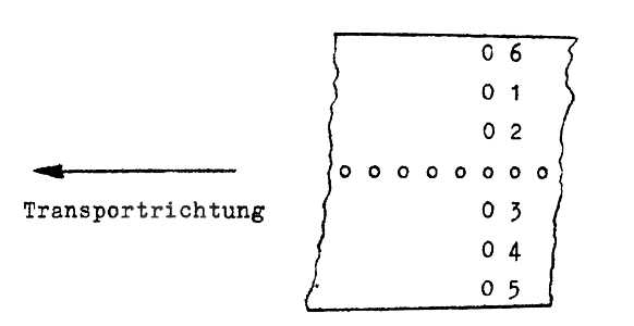

Weitere Tastens
           123456
:;	001111	0 6
?/	010011	0 1
].	010111	0 2
[,	011011	0 0 0 0 0 0 0 0
Vv	011111	Transportrichtung	0 3
Oo	100011	j	0 4
Xx	100111	0 5 


Bemerkung: Die Ziffern in den obigen Säulen beziehen sich auf die entsprechenden 
Löcher im Lochstreifen. Bei "0" ist kein Loch vorhanden, eine "1" 
stellt ein Loch dar. Während der 4-Bit-Abtastung werden nur die Zeichen an 
den Stellen 1 bis 4 in die Rechenmaschine gegeben. Alle 6 Zeichen werden nur 
eingegeben bei der 6-Bit-Eingabe. Mit Ausnahme des Tabulierungs - und 
Zwischenraumzeichens gelangen keine Bedienungszeichen in die Maschine. Bei Lesen 
des Tabulierungs- oder Zwischenraumzeichens werden entweder 4 oder 6 Hits in 
Abhängigkeit von der Stellung der 6-Bit-Eingabetaste eingelesen.