Log of 2009 events
July 8, 2009
Aug 26, 2009
Sept 30, 2009
Oct 14, 2009
Oct 21, 2009
Dec 9, 2009
July 8, 2009
August 26, 2009
Sept 30, 2009
We took a 10 second movie of the RAMAC arm in motion, converted to .wmv format in two resolutions
October 14, 2009
John Best reports that the RAMAC clutches:
Back to the RAMAC Restoration Room
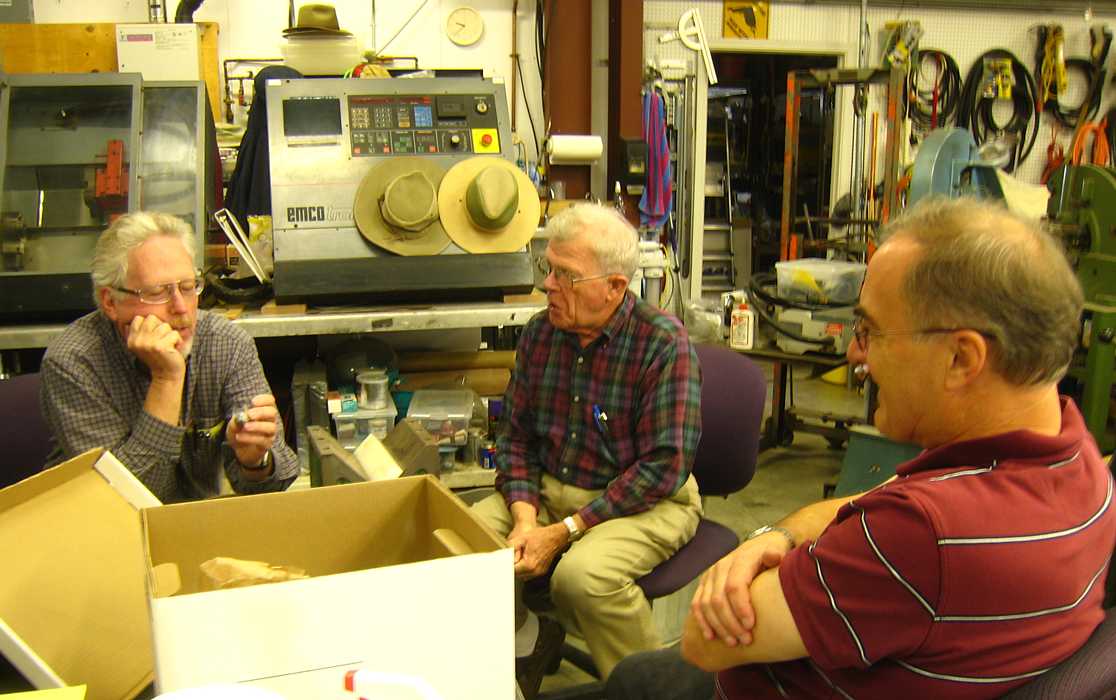
It is interesting, these guys are antique car buffs, taking 'em apart to fix 'em.
They each seem to have a garage full of tools, used frequently. They are comparing
parts of this RAMAC to parts of antique cars.
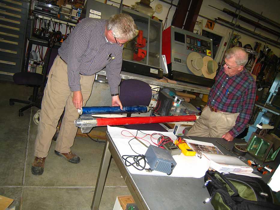
Oct 21, 2009 at Grant Saviers' work shop on Mt. Hamilton Road
OOPS - a distraction, what is that long red thing? A two stage rocket that went
42,000 ft straight up.
Ah - back to "business"
Would you believe we didn't have any parts left over? ;-))
Your correspondent has been busy,
then abroad :-)) then sick :-((
Dick Oswald said that he was taught a course by Fran Underwood, architect of the 1401 who spoke at the
50th Anniversary of the 1401 Announcement held at CHM November 10th.
2 hour presentation
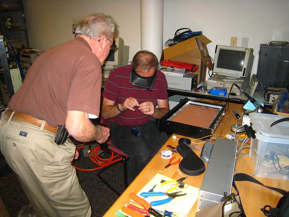
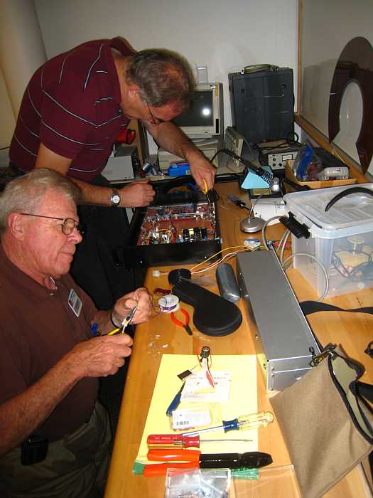
John Best, Dick Oswald, Dave Bennet and Joe Feng have designed and made a black box
to operate the RAMAC mechanicals. (They havn't powered it up yet, "the smoke test" ;-)) "
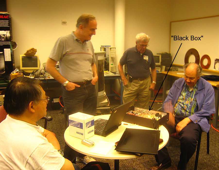
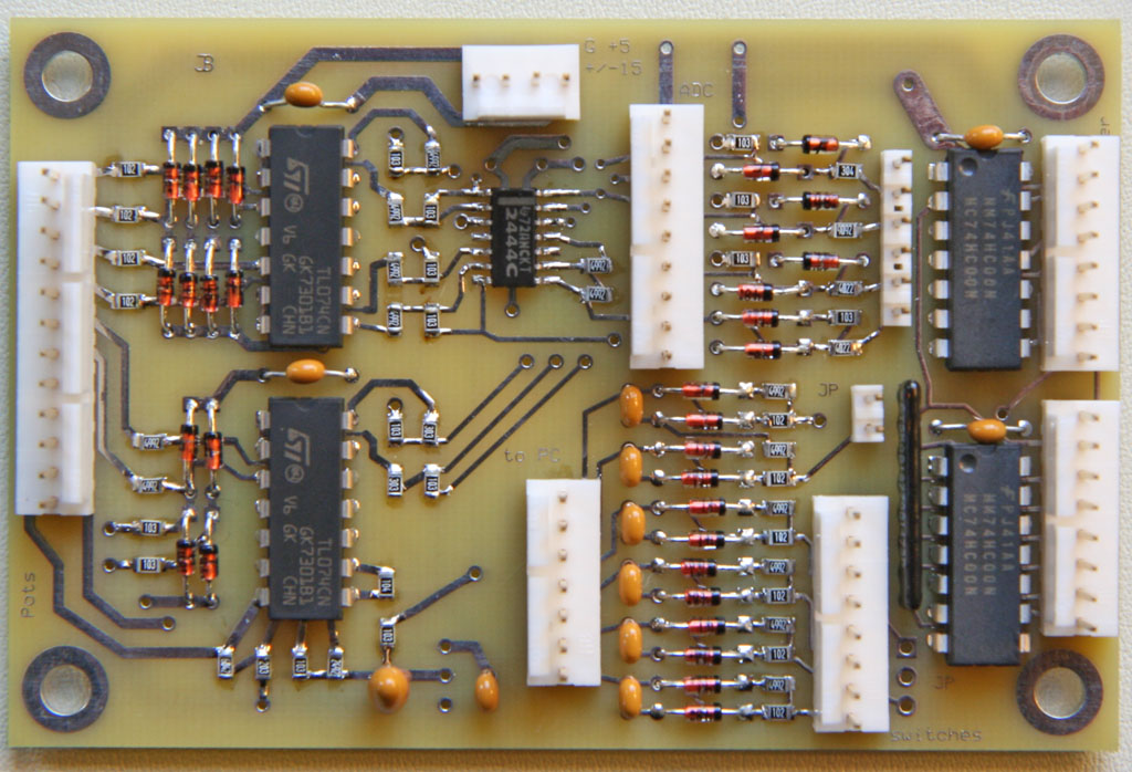
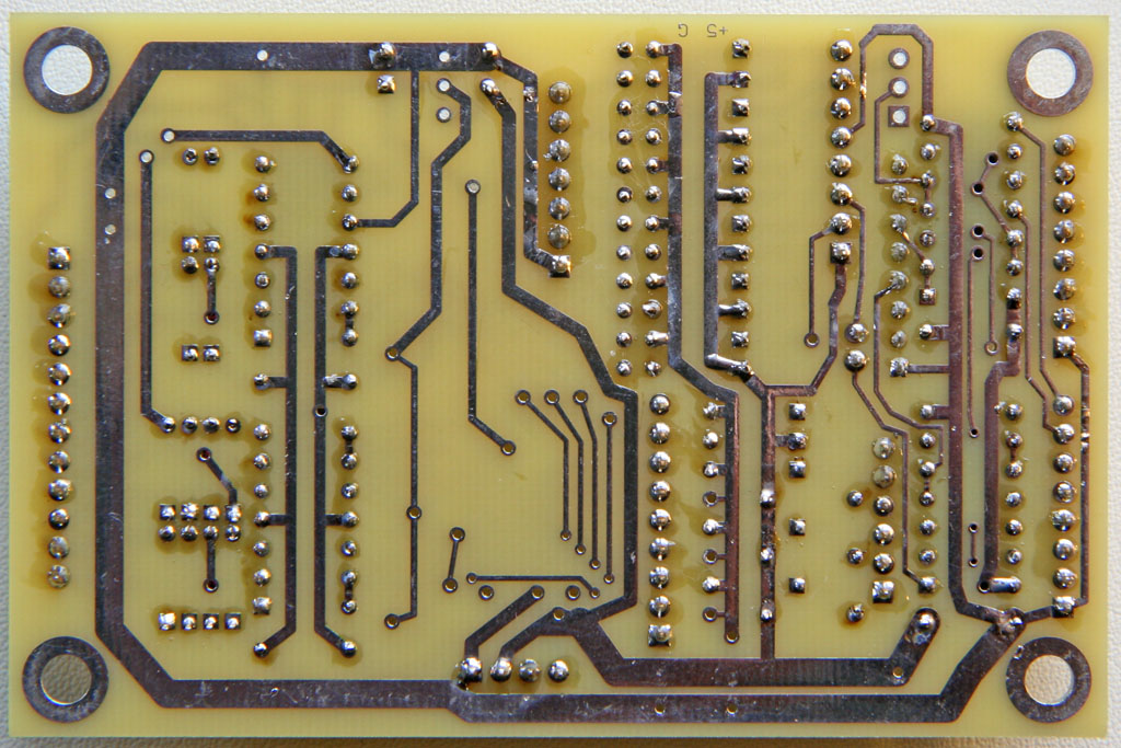
John Best has promised a better picture of the electronics :-))
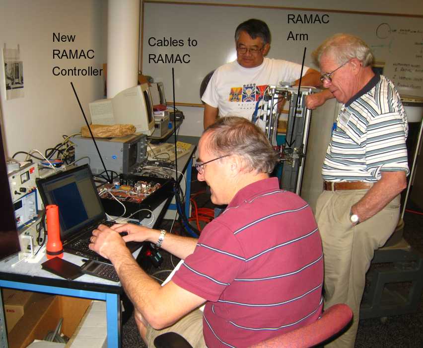
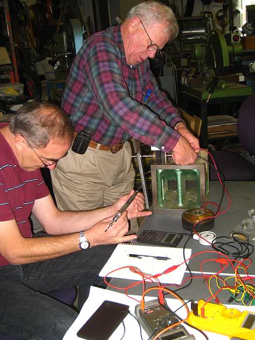
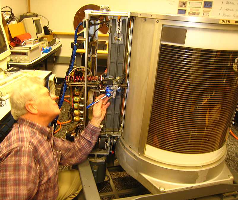
Ed Thelen visited the RAMAC project. Left to right, John Best, Joe Feng, and Dave Bennet
were present. John Best was
using his laptop to control his RAMAC controller (see pictures above) which was controlling
the RAMAC arm (with the read/write heads).
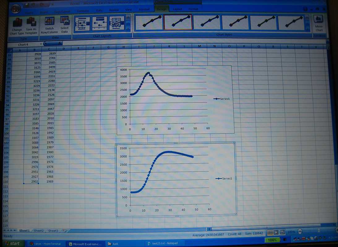
Here is some engineering data (50 years ago it would have been IBM Confidential)
October 2009
Oct 14, 2009
Oct 21, 2009
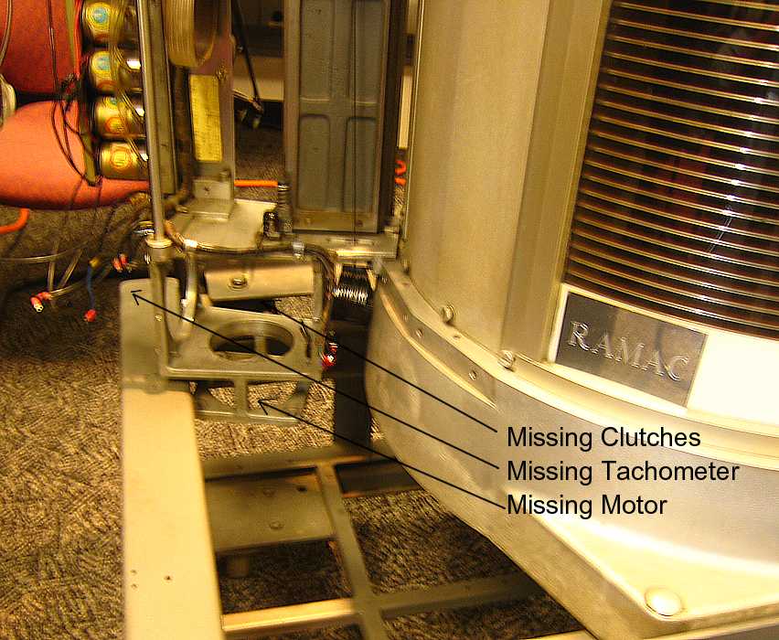
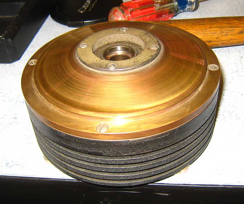
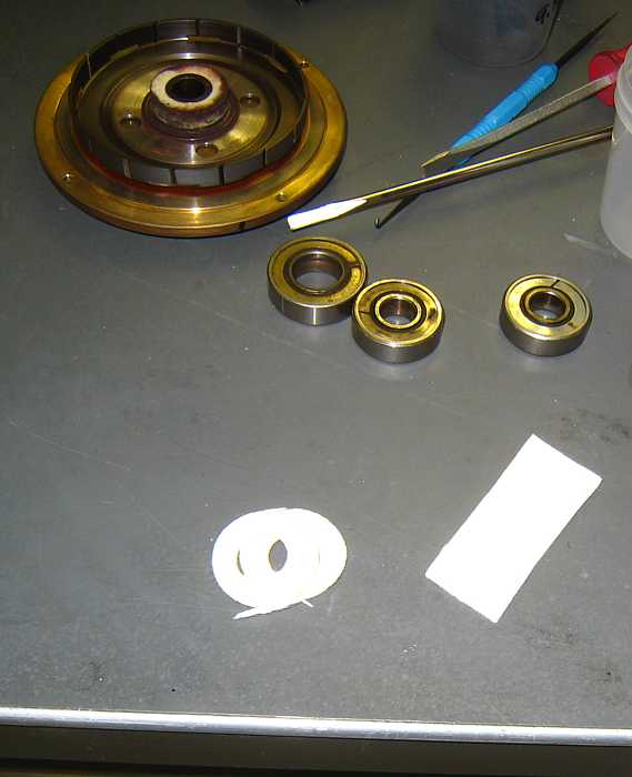
The clutches, motor, tachometer had been removed from the RAMAC,
and were on a work bench.
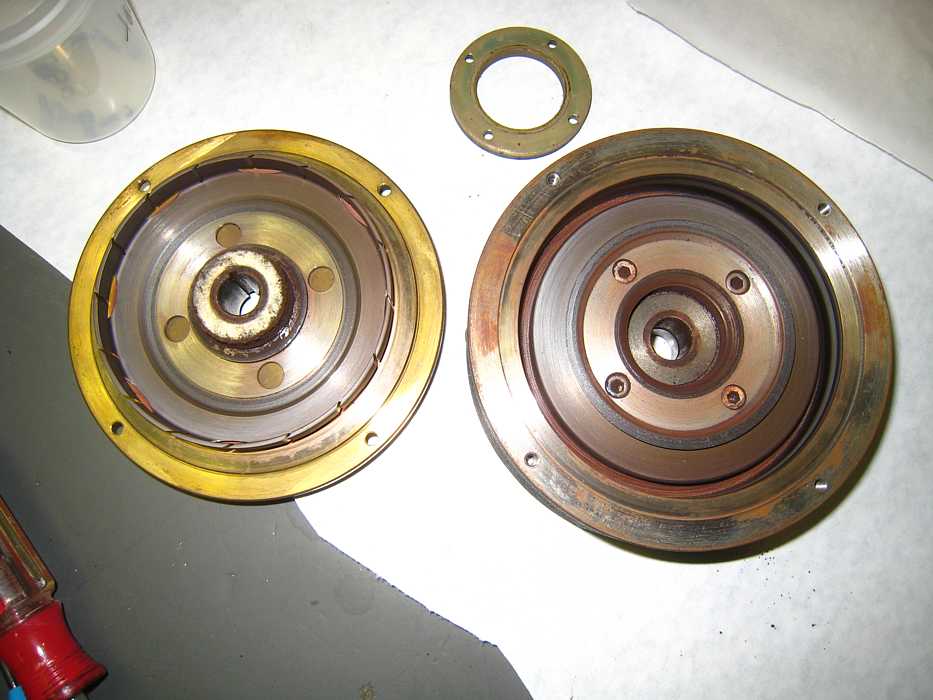
before
now
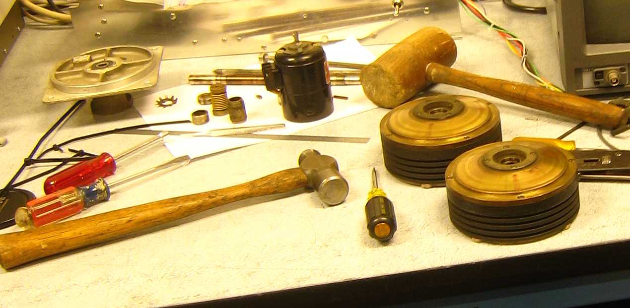
clutches and tach
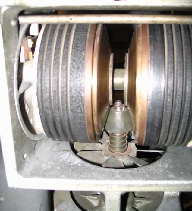
This image shows a clutch electrical contact slip rings, connected to the
solenoid coil inside
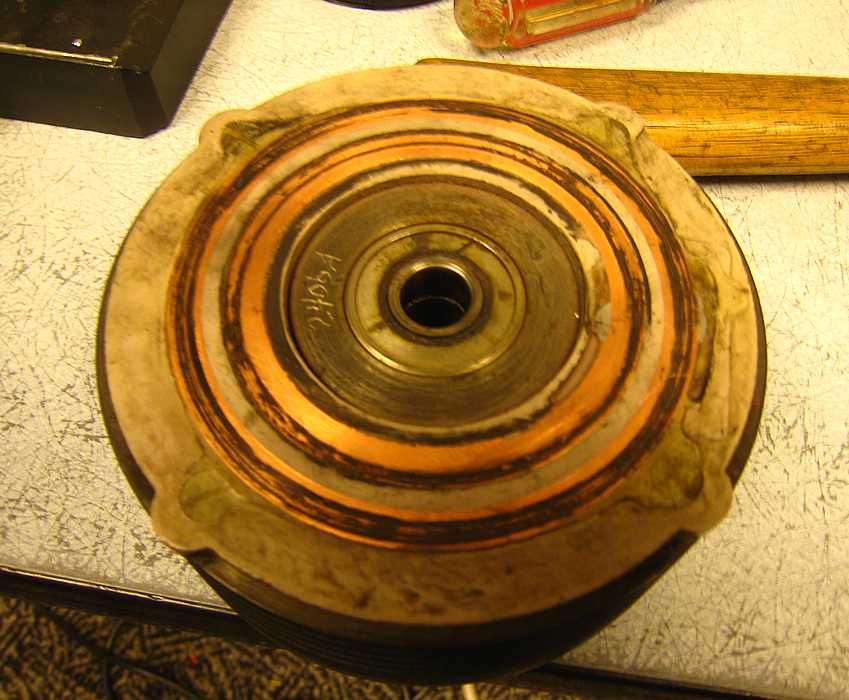
These are the fixed contact to feed the slip rings,
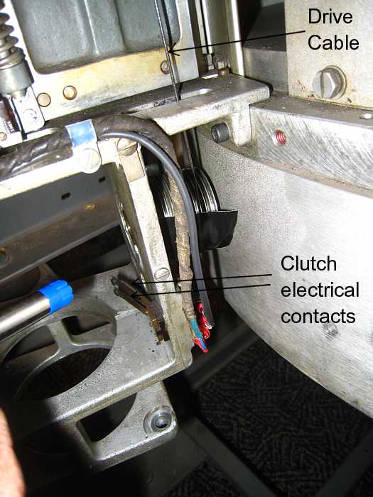
This is the driven end of the clutch, it rotates freely UNTIL a current,
maybe 1 amp, is driven through the slip rings (next picture) then it torques
the other part of the clutch, causing pull on the drive cable (above)
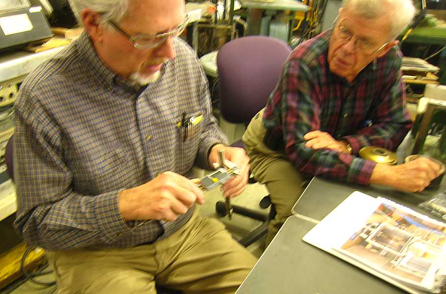
John Best is trying to measure resistance (320 ohms) - often contacts epoxy.
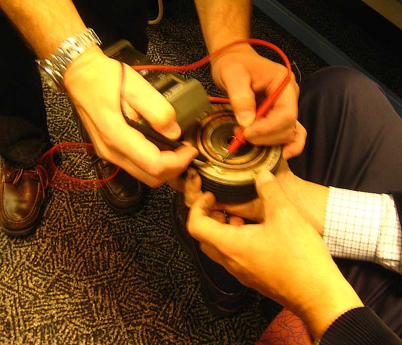
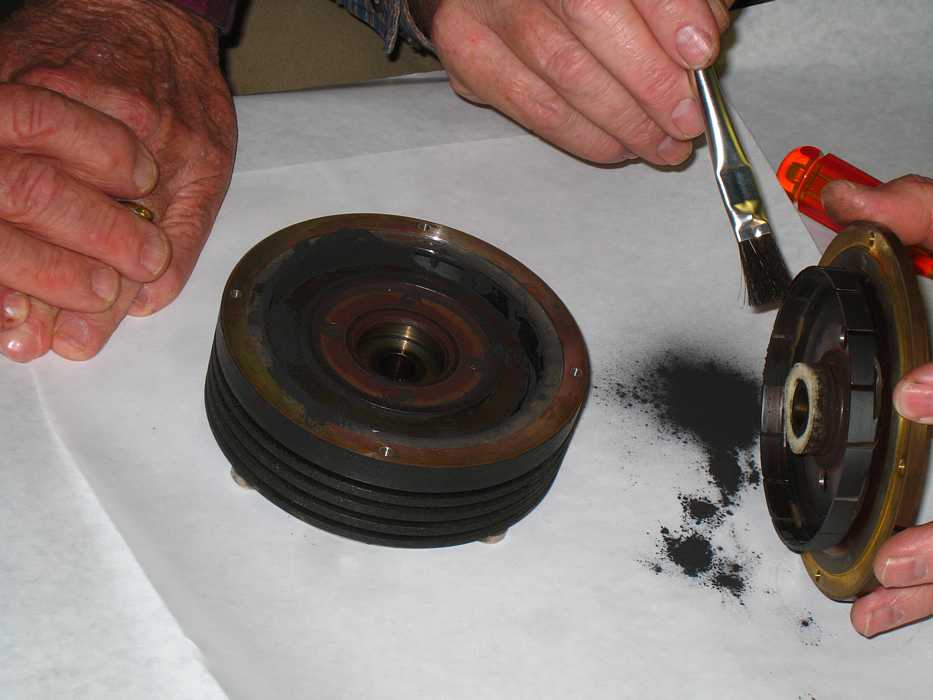
Dick Oswald had the hots to open the clutch, John Best was more cautious -
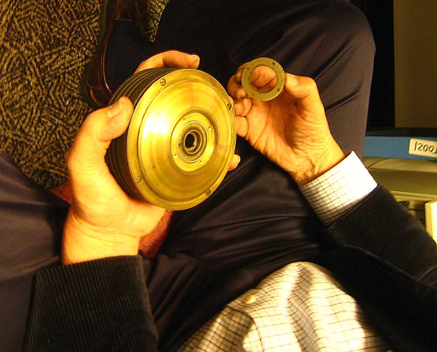
Its Open! Dave Bennet (left) looking at the driven plate
(the conical section (would have been under the bottom) has been removed.)
Near the tips of his fingers is the felt seal to keep the iron powder in the clutch.
The part near Dick Oswald's fingers contains the iron rotor and coil.
We met at Grant Saviers' workshop with the intent of
repairing the two clutches used in the IBM RAMAC 350 rotating
storage device.
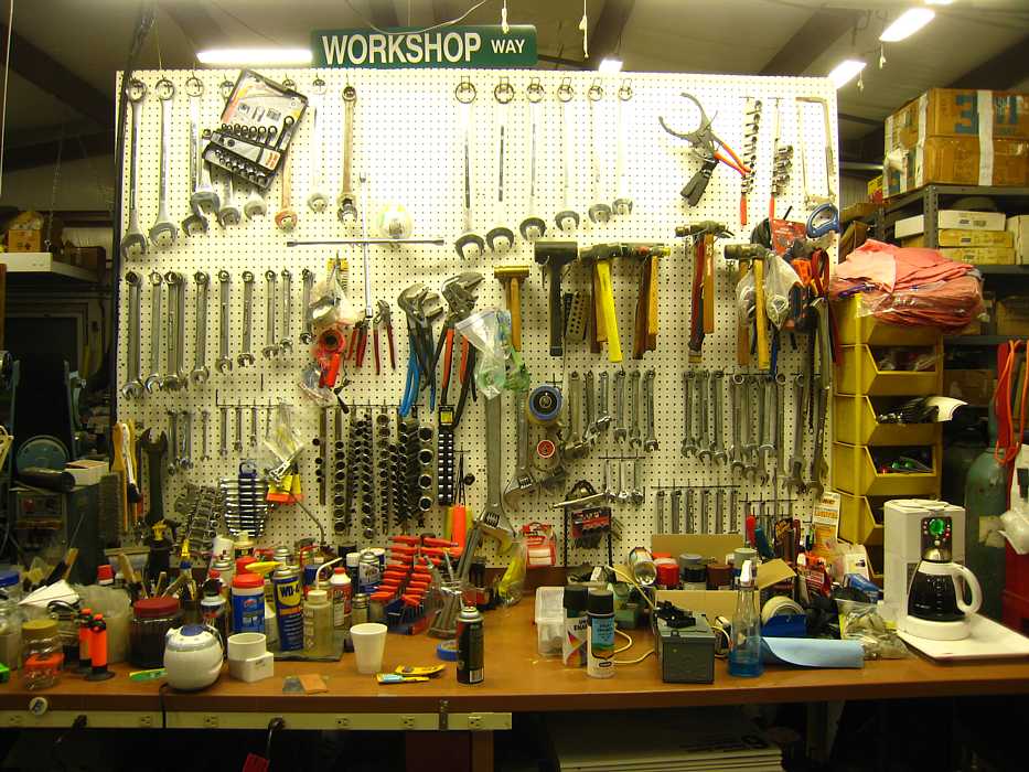
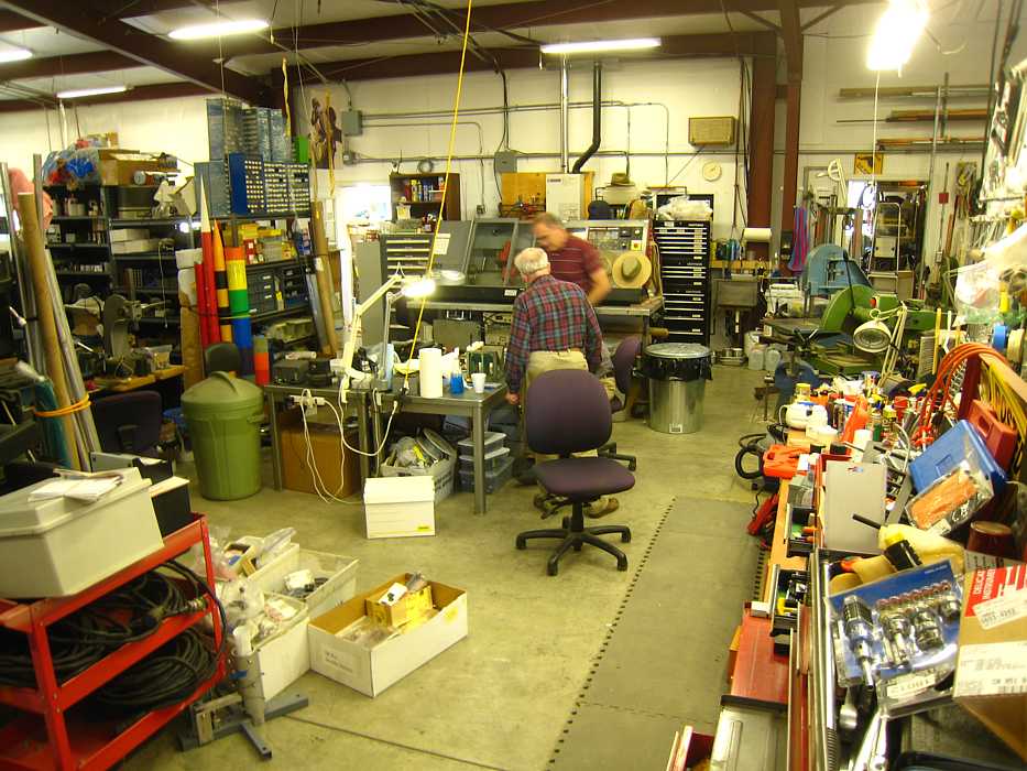
This might be called the heart of Grant's work shop, "rather well equipped" ;-))
- better picked up than many?
and the visitor's area
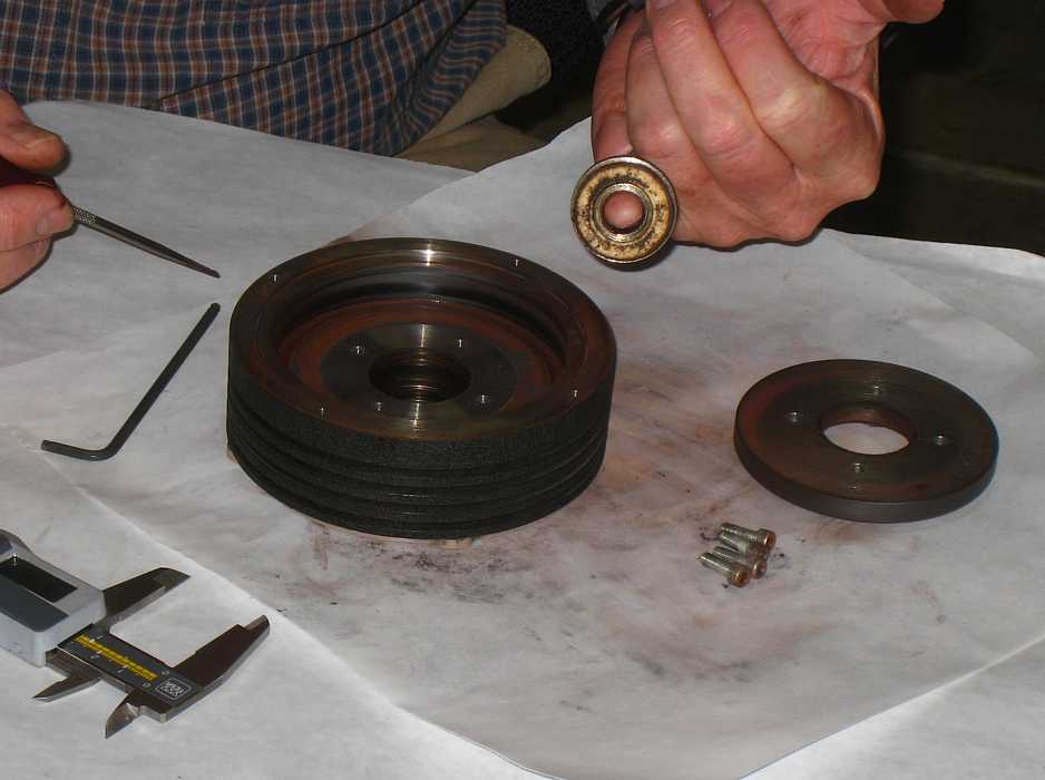
Christmas comes in many forms - here Grant Saviers (left) receives a RAMAC dual clutch
assembly for play for a day from Dave Bennett and John Best (right)
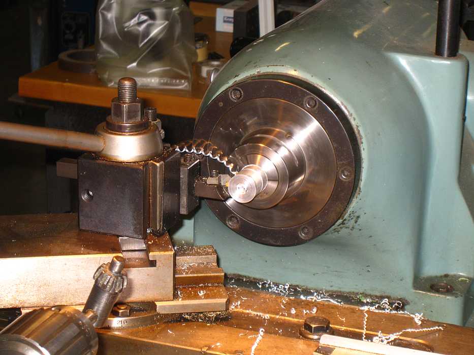
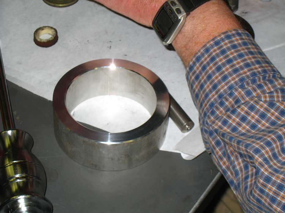
Ah Look - a damaged shaft to be rebuilt. Some frozen bearing had removed
maybe 0.003 inches. How lucky can you get? ;-))
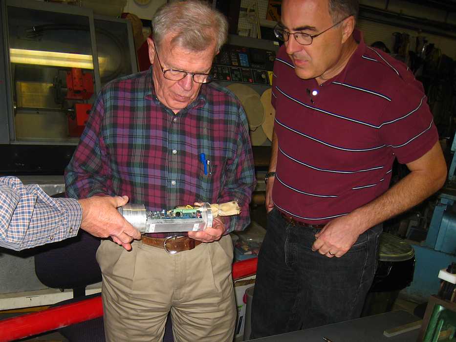
The red shaft is the top stage. Grant is holding the "engine", with rocket
propellant, pressure container, and nozzle.
Here is the instrumentation/control package. Battery, GPS unit, 3 axis accelerometer,
a 460 MHz transmitter for telemetry and tracking,
and a black powder charge for popping the parachute. Aren't integrated circuits
great !!
We then got into a discussion of amateur rocket propellants
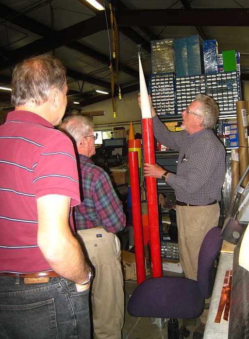
Grant inserting the nose cone. His left hand is just below an area of heat bubbled
red paint that got too hot at Mach 2.3.
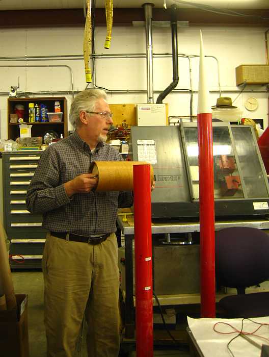
Here Grant holds a brown cylinder which is the allowed volume for various student
rocket projects. These projects include autonomous vehicles to get from a
launched rocket back to the launch area. How about that for miniaturization?
From Grant
From Grant about the payloads:
The "official" web site is http://www.arliss.org/

The clubs web site is http://www.aeropac.org/

Several types in the 6" dia x 11" format - examples but not constrained except
that return from 12k agl ft ejection to specified lat-lon must be autonomous:

powered & not powered gliders/airplanes
moon rovers (to earth by parachute)
retrievers - pick up an immobile beacon and take it to the L-L point
guided parachutes, parafoils, etc.

Smaller rockets fly one "cansat" and 3 "cansats" fit in the payload
container I am holding - limit 1lb and about the size of a coke can plus parachute.
The experiment is anything except vertebrae animals.
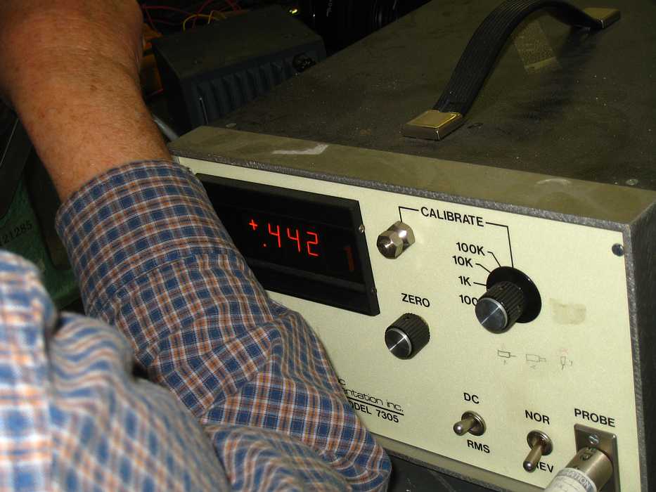
John Best and Dave Bennett had taken some torque vs current measurement of
the two clutches while mounted in the RAMAC - a rather difficult environment.
Maybe we should do it again in a better lab environment, isolated from many other variables.
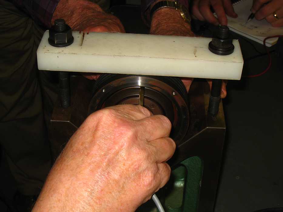
"We" will do static torque measurements from this side
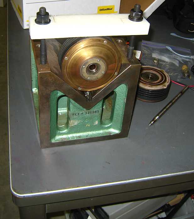
and apply current to the magnetic coil from this side.
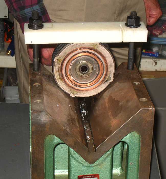
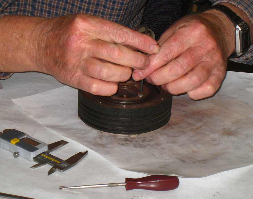
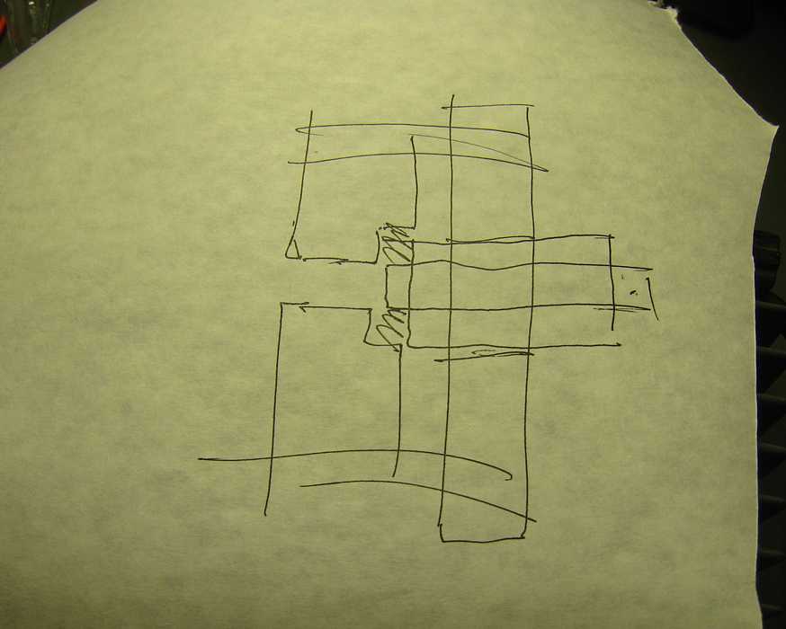
And here we have the heart of the torque measuring. Grant made a rod to clamp
perpendicularly onto the center shaft, marked with dimples at 2", 5" and 10" radii.
John Best has set a current which Dave Bennett is applying to the slip rings. John is
pushing a force measuring instrument at the 5" dimple, measuring the force to cause
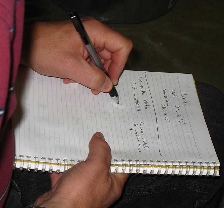
the clutch to slip. And the pen and paper.
The measurements were repeatable and in line with the measurements made previously
on the intact RAMAC
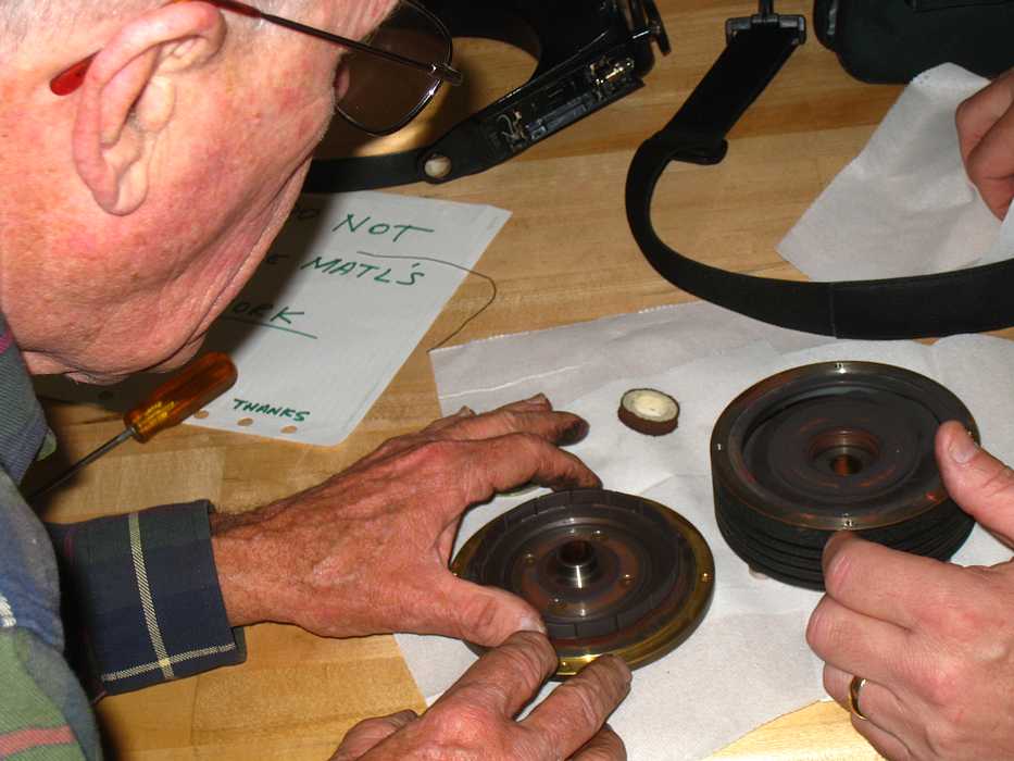
Enough of this Physics Lab stuff, time for fun - take it apart!
Hmmm - is this torque safe??? Will I break a screw?
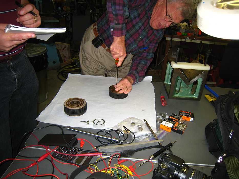
Ah - look at that :-)) The whole goal of the clutch is to control torque to that
slotted low inertal mass rotor. (The rotors of the 729 clutches were not slotted.)
Visible at the center of the rotor is the felt washer to keep the black magnetic
powder where it belonged -
All cleaned up, screws in one plastic cup, magnetic powder in another.
Visible is the deep ring grove that the rotor spins in. One side of the grove will
have one magnetic polarity, the other side the other polarity, from the current in
clutch coil winding. The magnetic powder stretching from pole to the other, with the
rotor in the middle.
and the logbook
Grant removes the inner pole piece to get at the bearings supporting the
clutch on the main shaft.
Ah - look at that :-))
and the inner felt
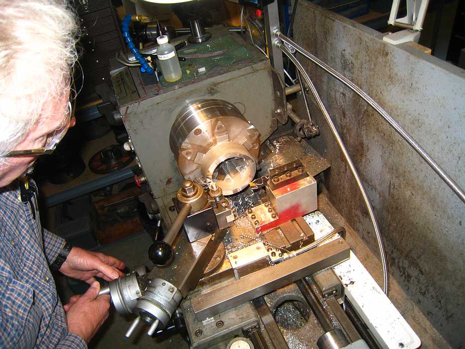
Grant making a nice supporting structure to support the clutch while
pressing out the bearings. This is not a casual operation - serious first class.
and a nice little grove with different radius when we turn the clutch over
And a proper pusher thingie - OK, so I ain't no machinist :-((
You give it a name !!
Kinda pretty ain't it?
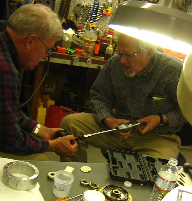
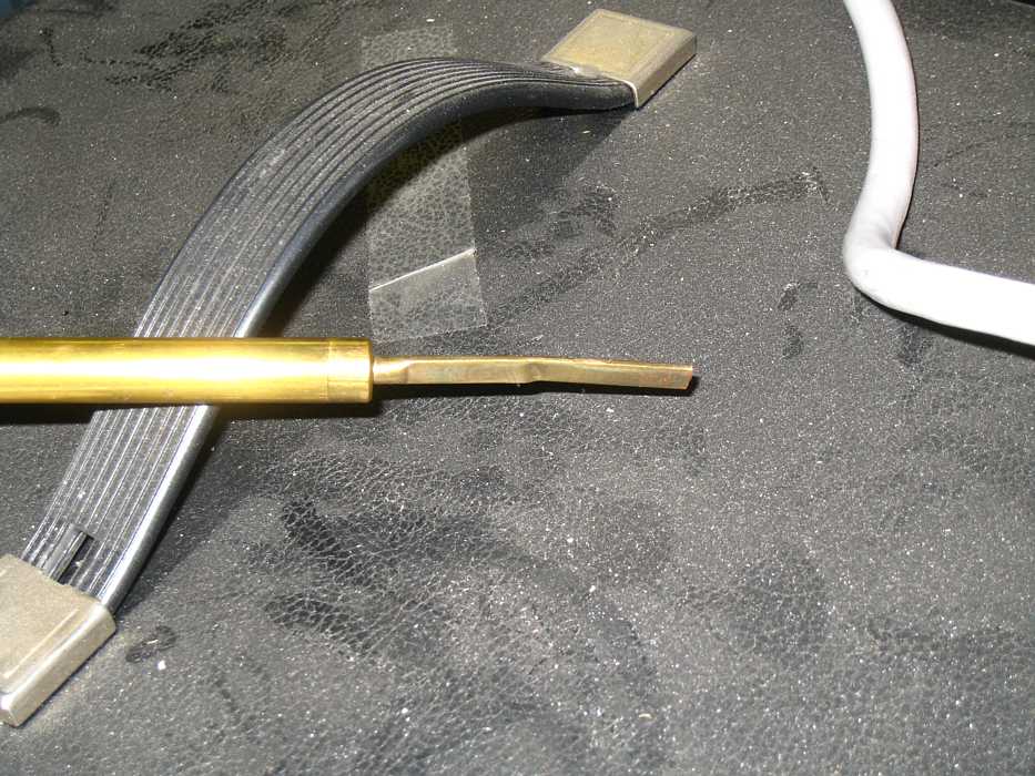
And sometime a pulling impact is desired. Here Grant is sliding the shiny slug
back along the shiny rod until it hits a stop - and out comes the bearing :-))
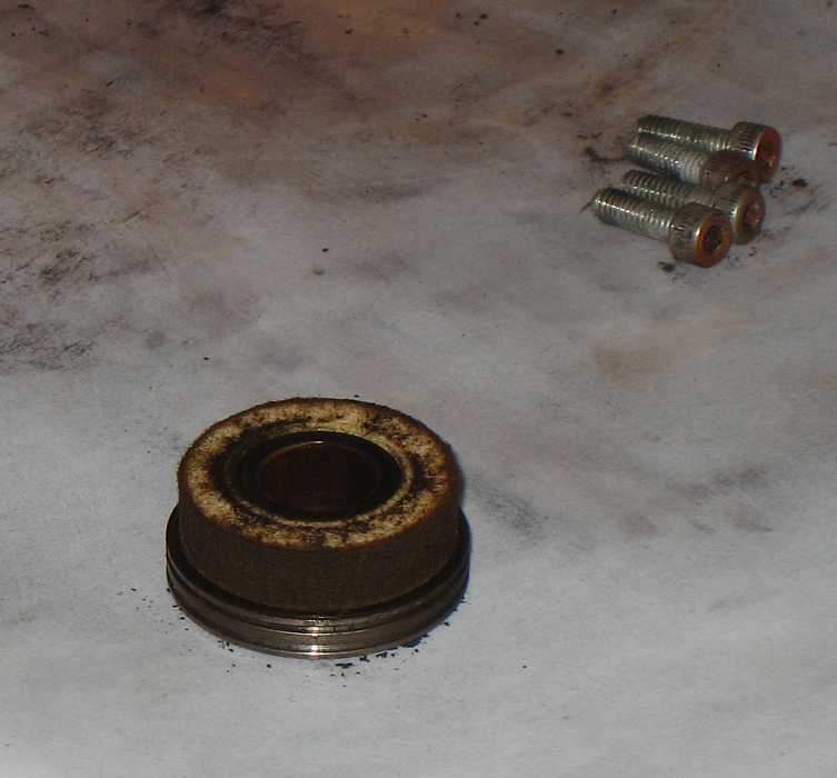
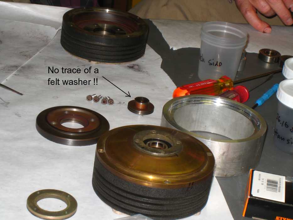
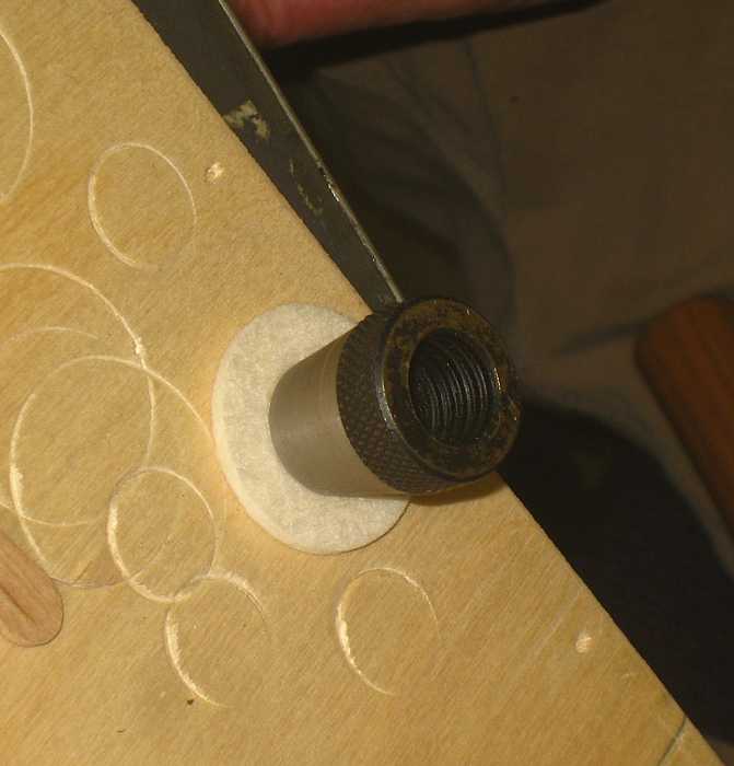
OOPS - Hello there - the second clutch had NO felt washer to:
Grant says punching felt to make washers properly concentric is "interesting".
It took 3 days to make this jig for the 729 felt washers, (a different size)
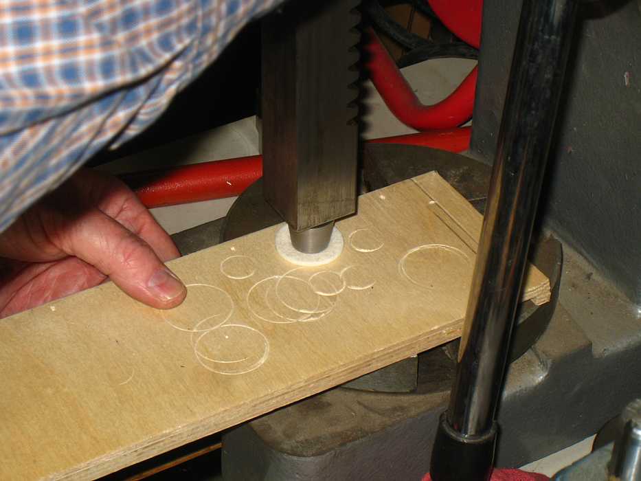
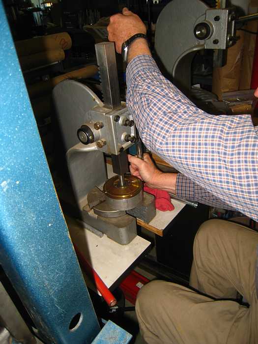
Here a felt has been punched for outside diameter. The die here is placed
as concentrically as possible by eyeball. Unfortunately, if you strike it
with your brass hammer - it seems to shift.
But gentle vertical pressure in an arbor press does just fine :-))
Grant says he has a magnetometer - lets measure the magnetic flux in the gap
with different currents at different positions.
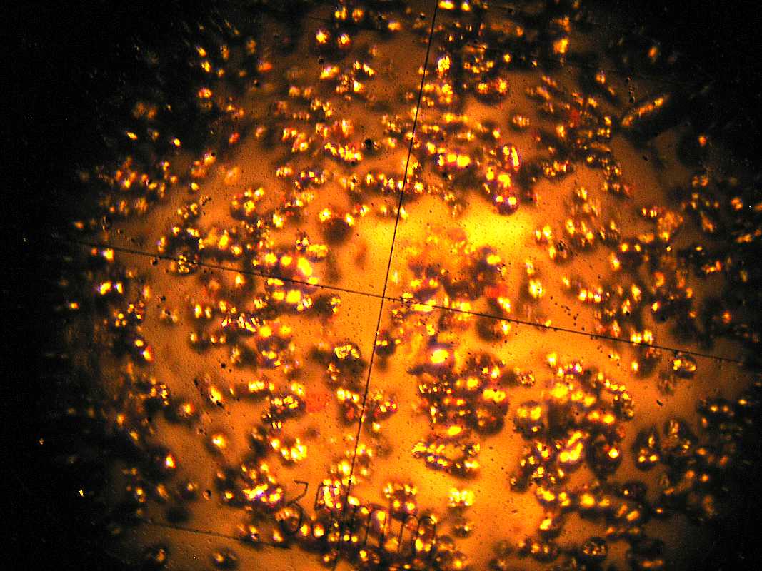
Grant says that a method of making this round iron powder is to boil iron in a
really hot flame or arc (probably in a neutral or reducing atmosphere). Here are
Internet sources 1,
2
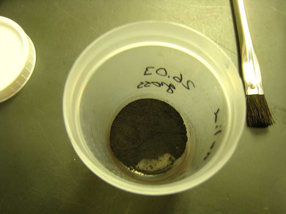
Let's look at the powder through Grant's microscope. It was stored in cups like
this during disassembly - really not much per clutch, on the order of 20 grams,
about the weight of 20 dimes.
OK - This image was made through the microscope eyepiece onto my little pocket
Canon image stablized camera. With normal 35 mm focal length, the lit image was
a small part of the view - someone suggested optical telephoto,
much better but rather dark. I've lightened it up in post processing.
Well, the new bearings (Timken) had been pre-ordered, and delivered,
we now have good felt washers.
Time to put things back together. There are rude jokes about what to do about left over
parts :-(( Poor taste at the end of a long tense day?
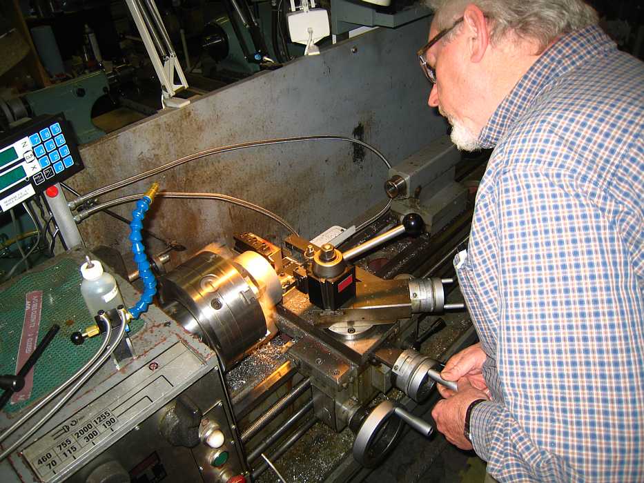
I believe Grant is pressing in a bearing, using 2 of the jigs he just made,
and his arbor press.
and this is not government accounting -
December
Dec 9, 2009
Present were Dave Bennet, John Best, Joe Feng, Dick Oswald, and Mason Williams.
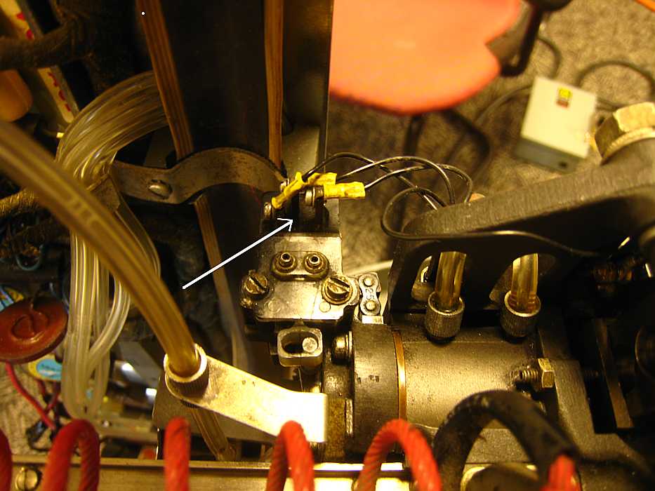
Dave Bennet examining the track detent switch
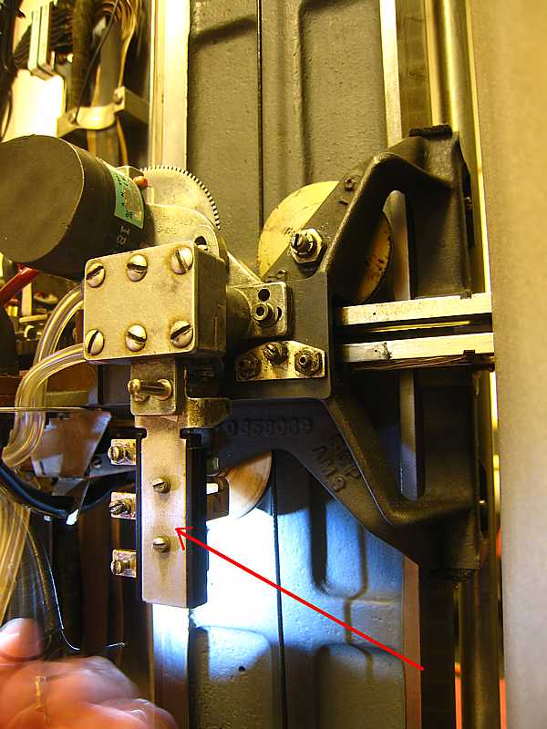
We haven't discussed this before. It is a three position switch - closed one way, open, closed the other way.
This verifies that the air operated track detent is either IN or OUT.
This is a similar switch that verifies that the disc detent is either fully IN or fully OUT.
For a quick refresher,
Here is John Best explaining some point to Mason Williams, a new member of the RAMAC Restoration Team
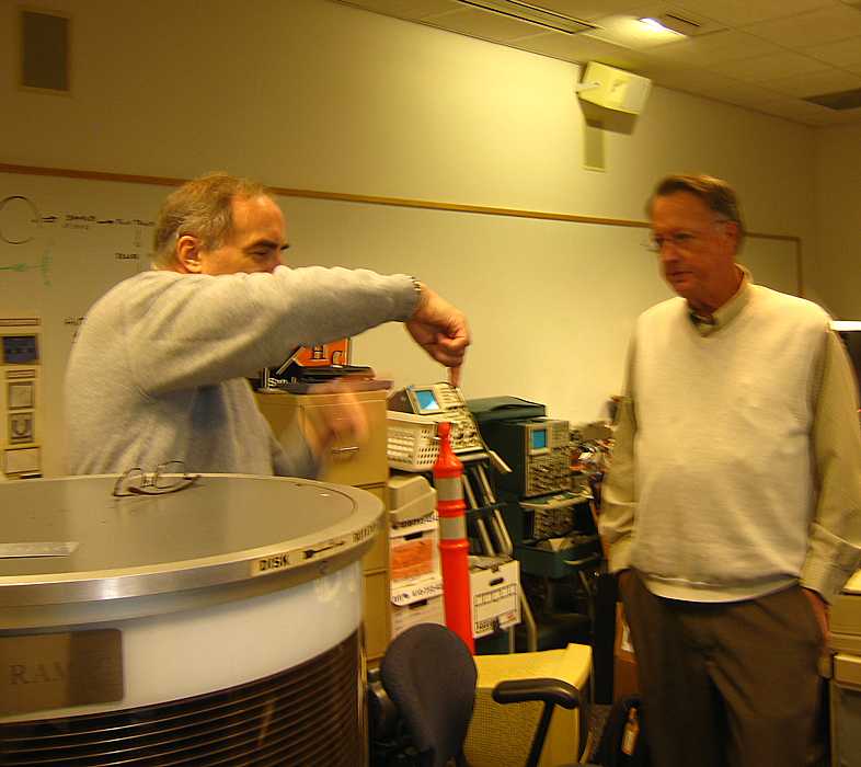
Mason Williams was introduced as a Cal Tech physicist, and seemed very familiar with magnetic clutches,
oersteds, B-H curves, and other easy to forget physics things.
Mason Williams showed me a movie he is making to demonstrate principles of the RAMAC.
This is a few seconds of the result of his 1st week's effort - very preliminary - about 750 K bytes, .wmv format
click here