Return to Home
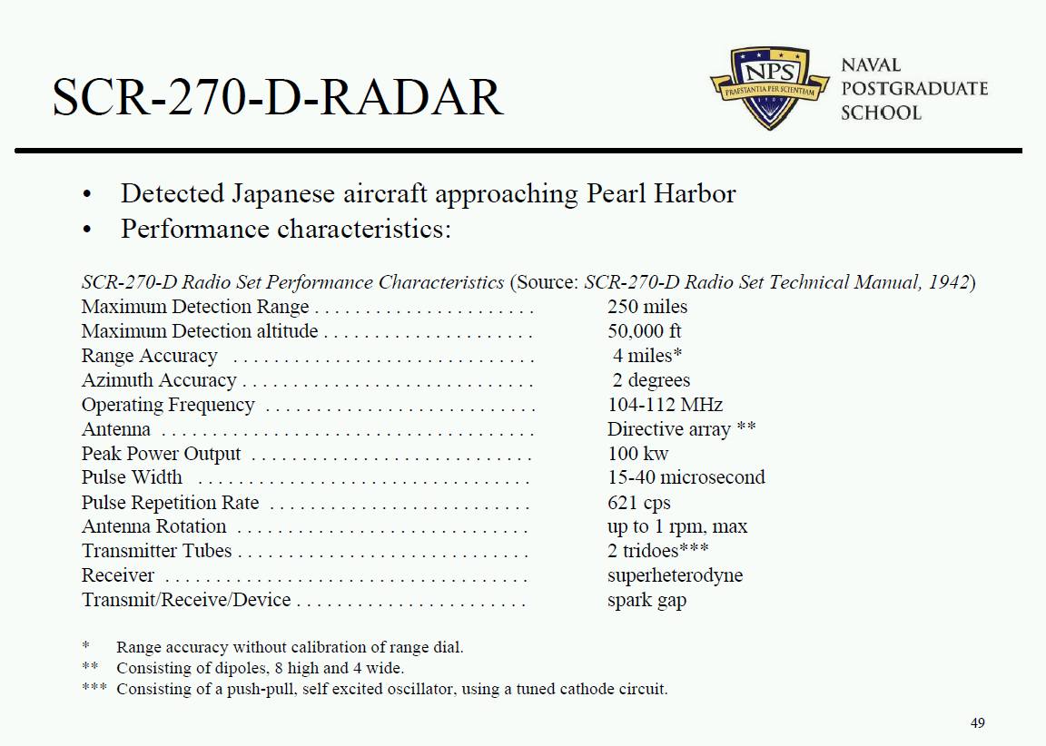
Purpose -Try to describe the U.S. radar which detected the Japanese planes
approaching Pearl Harbor Dec 7, 1941.
also see Wikipedia SCR-270 radar
Star-Bulletin
says the Opana Point radar site is 532 feet above sea level in the Kahuku mountain range,
IMS 2009 RF/Microwave Museum Photos has a picture of a
"Westinghouse WL-530, Water Cooled High Power Triode" Used in the SCR-270 radar.
Local copy here
Radiomusuem says
	WL-530
	Country:  	United States of America (USA)
	Brand:  	Westinghouse El. & Mfg. Co.
	- see also Canadian W.
  	Tube type:  	Transmitter Triode, liquid-cooling
	Tube ID = 54406

	Identical to 	WL-530 = 530 = GL-530 = VT-122
	Was used by 	Military and/or Government
	Filament 	Vf 7.5 Volts / If: 80 Ampere / -: Direct /
	Description 	Distilled-water cooled triode for pulsed operation.
		Thoriated-tungsten filament,
		 80A peak emission. 15KV peak voltage,
		8KW plate dissipation, 120MHz full ratings.
	Used in BC-400B of SCR-270 radar.
	Dimensions (WHD)
	incl. pins / tip 	95 x 241 x mm / 3.74 x 9.49 x inch
	Tube prices 	1 Tube prices (visible for members only)
	Literature 	Tube Lore, Sibley, USA 1996
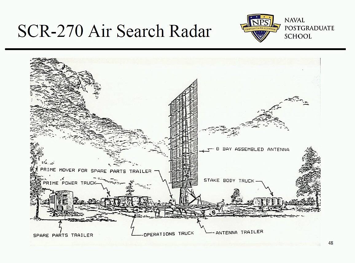
From Naval Post Graduate School, SCR-279-D site drawing,
page 48,
and Specifications, page 49,
from
Radar Fundamentals 5 MB .pdf
A Radomes.org presentation of the
SCR-270
From
http://www.ieeeghn.org/wiki/index.php/Milestones:Opana_Radar_Site%2C_1941
IEEE Global History Network, Milestones: Opana Radar Site, 1941
THE SCR-270 RADAR by Fred Suffield (1920-2001) was a Life Fellow of the IEEE.
(reformated)
|
|
|
Work on this first long-range search radar started at the Signal Corps laboratories at Fort Monmouth, New Jersey, in about 1937. A production contract was let to the Westinghouse Electronics Division in Baltimore, Maryland in 1940. And on December 7, 1941, this was the radar that detected the incoming aircraft at Pearl Harbor. Sadly enough, hardly anyone understood the capability or made use of the radar data up to and including December 7th.
The radar, by today's standards, would be classified as crude, but considering our lack of knowledge of pulses, high frequency, pulse modulators, displays, human factors, etc., it was a surprisingly good unit. It maximum range, 150 miles, and consistent echoes were received at this range. When sited on a cliff or bluff, echoes beyond 150 miles were received.
The operating frequency was 106 megacycles, a high frequency for 1940. With a wavelength of about 9 feet, propellers on aircraft became excellent reflectors.
Site buildings and power
|
The entire radar occupied four trucks. One of these van type trucks housed the generator and the transmitter power supply. Another was a stake body truck that carried the antenna elements when the radar was being moved. A third was a prime mover that pulled the antenna mount. The fourth was the operating van, it housed the transmitter, modulator, receiver and indicator.
Each operating van had a spare receiver and spare scope; otherwise, everything was so conservatively designed that service was almost unheard of, except for occasional tube replacement in the modulator.
To describe the contents of each truck, one should start with the power unit. This housed a 76 horsepower gas engine driving a 31KW three-phase 60-cycle generator. The engine exhaust went straight up, through a rather ineffective muffler, out the roof of the truck.
|
Transmitter ( and its power supply and modulator )
|
The transmitter power supply was a monster. It was about 4' high, 5' wide and 6' deep, and only supplied 15KV at .5 amp from a full wave rectifier, a choke and a .5 mfd capacitor. Clever design points in the power supply involved design of the type 531 rectifier tube, about 3" diameter and 7" long. The bottom, at the plate connection, was a cast finned structure that seated into a 3" diameter ring mounted directly on top of the high voltage insulators on the transformer, thus, no plate leads, caps, insulation and support problems.
The heart of the system was of course the Operating Van. The transmitter used two water cooled triodes, type 530, resonant plate line, with the grids held off at about -4500 volts, pulsed up to "0" bias to oscillate. The 15KV-plate voltage required a dual wound ceramic coil to isolate the plates from the grounded water supply, distilled water to minimize leakage current and the addition of ethyl alcohol in the winter as anti freeze.
|
RF coupling antenna to transmitter and receiver
|
The tower was rotated by controls from the operating position, and RF was carried on a 3" spaced copper tube parallel line to the base of the tower in a resonant line condition, terminating in a single turn loop at the base coupled to another single turn loop feeding up the tower.
|
Antenna(s)
|
The antenna tower unfolded from its transportation position to be a triangular tapering tower rising 55' above a circular 8' diameter base. The base plate was remotely rotatable, from the operating truck, thus, steering the antenna. The actual elements were a series of 36 half wave dipoles, arranged in three bays, each bay had 3 strings of horizontally polarized 4 pairs of dipoles, all 36 backed with reflectors. All tuning on early models was by shorting bars on parallel lines and line stretching "trombone" sections. In 1940 there was serious doubt that a 106-megacycle antenna could be designed, built, assembled and tuned in a factory.
Westinghouse had a field station on Sandy Hook, New Jersey, offering a distant view over the water entrance to New York Harbor to three large gas storage tanks in Brooklyn. The antenna tower was physically aimed towards the center tank, the radar put on the air, and one man watched the scope in the operating truck, and one climbed the antenna tower with a 4' length of 1 x 2 wood stick. The man on the tower banged away at trombone sections and shorting bars and the man 150' away yelled at him to indicate improvement in the target. When the center tank was a good target and the side one small, the antenna was tuned!
The antenna was then rotated to look towards the Glen L. Martin plant in Baltimore, where they almost always had aircraft in the air in test. This provided a crosscheck on performance and opportunity for final tune up. After about 25 sets, we had enough data to pre-position most adjustments, and ultimately went to a screen reflector and pre-cut elements.
|
Receiver
|
The receiver was a superheterodyne, with a special tube, the A-5588-A, an RCA experimental electron multiplier, in the front end. While Westinghouse built the modulator, power supply, transmitter and other items, RCA supplied the receiver and I believe Colonial and RCA the indicators.
|
Display
|
For those accustomed to reading azimuth from the rim of a PP1 scope or from digital read out, we had a different system. We had 3" high numbers painted on plates attached to the 8' diameter rotating tower base and read the azimuth through a window from the operating truck, using at times binoculars, or just plain estimating if mud obscured the numbers.
There is no description of the radar display other than azimuth above. I "presume" it was
an "A" scope with "main bang" on the left and time going to the right,
with the detected signal rising above the base line. Range would be distance (time) from
the "main bang" ;-))
|
|
|
From: USAF-RADARSTATIONVeterans@yahoogroups.com
Subject: R S V Digest Number 5042
1b. Re: Old Radar Equipment
Posted by: "Richard Miles" rmmiles@comcast.net
Thu Jun 21, 2012 12:07 pm (PDT)
|
|
|
When I arrived at Okino-Erabu-Shima an island north of Okinawa (624th AC&W Sqdn) on August of 1952 our only radar was an SCR-270. This radar was very much like the Pearl Harbor radar back in 1941. The radar operated in the 100Mz frequency range .
We nursed this radar along for about one year and we finally received an AN-TPS-1B radar.
Site buildings and power
Transmitter ( and its power supply and modulator )
|
The radar used water-cooled transmitter tubes
|
RF coupling antenna to transmitter and receiver
|
and had open transmission lines between the ops building and the Bed-spring type antenna ...
T/R switch was a couple of nails mounted on the transmission lines. We set the gap between the nails so that they would arc on each transmitter pulse and protect the radar receiver.
|
Antenna(s)
|
Bed-spring type antenna that rotated at one RPM.
The dipoles mounted on the antenna were rusting to the point that they would fall down and we would have to bailing wire them back into their position.
|
Receiver
Display
|
|
From
http://www.ieeeghn.org/wiki/index.php/Milestones:Opana_Radar_Site%2C_1941
|
|
|
Site buildings and power
Transmitter ( and its power supply and modulator )
RF coupling antenna to transmitter and receiver
Antenna(s)
Receiver
Display
|
|
From
http://www.ieeeghn.org/wiki/index.php/Milestones:Opana_Radar_Site%2C_1941
|
|
|
Site buildings and power
Transmitter ( and its power supply and modulator )
RF coupling antenna to transmitter and receiver
Antenna(s)
Receiver
Display
|
|
From
http://www.ieeeghn.org/wiki/index.php/Milestones:Opana_Radar_Site%2C_1941
|
|
|
Site buildings and power
Transmitter ( and its power supply and modulator )
RF coupling antenna to transmitter and receiver
Antenna(s)
Receiver
Display
|
|
SCR-270B