The article I wrote for the July, 2009 Touch & Go, "Airway Light Beacon Archaeology," explained my interest in finding the remnants of the beacons that guided pilots at night from the late 1920?s into the 1950?s. During that same period, pilots were guided in instrument flight, and in daytime visual flight, by the Four-Course, Low-Frequency Radio Range. The beacons and radio ranges were the navigation aids (or navaids) that were indispensable in enabling the airplane to evolve from being a marginal, fair-weather, daytime-only supplement to America?s transportation system to becoming a major, all-weather transportation provider in the course of 20 years.
The first experiments in using radio for both air navigation and two-way communication were conducted by the U.S. Air Mail Service in 1919 and 1920 but were soon discontinued. The establishment of the Aeronautics Branch in the Department of Commerce in 1926 brought renewed efforts in radio communication and navigation. The first seven two-way communication stations, developed by the National Bureau of Standards, were installed by October, 1928. That system expanded to 68 stations, spaced approximately 200 miles apart, by mid-1933.
The Low-Frequency Radio Range (LFR), also known as the Four-Course Radio Range, the A-N Radio Range or the Adcock Radio Range, was developed in the late 1920?s after some unsatisfactory experiments with navigation by both ground-based and airborne radio direction finding. One account attributes development of the LFR to radio engineers of the National Bureau of Standards, borrowing from European systems with improvements contributed by the U.S. Army Signal Corps.1
Another account states: "Late in the fall of 1926, the Ford Motor Company was engaged in ferrying air freight between its Chicago and Dearborn airports. The first of the famous Ford Tri-motor planes was placed on this run early in 1927, and it was in this year that a young Ford radio engineer named Eugene S. Donovan patented the first four-course, loop-type, low-frequency radio range. Two of the radio ranges were installed by the Ford Co., one at their Chicago Lansing Airport and one at the Dearborn Ford Airport. Both proved quite successful in improving the bad weather reliability of the cargo flights. The following year, after intensive and exhaustive tests, the Federal Government began installing a vast chain of LF/MF ranges crisscrossing the Nation to provide radio highways of the air. For each installation patent permission was given, without royalties, by the Ford Motor Co. so that these ranges could be installed in the public
welfare.2
Irrespective of how the LFR was developed, it was soon considered "indispensible" to the development of aviation. Some who considered Ford the developer of the radio range proclaimed it to be a more significant contribution to aviation than Ford?s famous Tri-motor airplane.
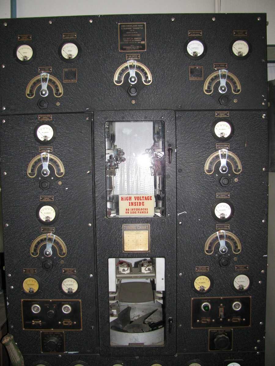
The four-course radio range used two loop antenna systems to transmit two overlapping figure-eight patterns.
Transmission frequencies were in the 200 to 410 kHz range with some military LFR?s operating at as high as 536 kHz.
One pattern transmitted a Morse code letter A (? ? ) and the other, with the pattern oriented at approximately right angles to the first, the code letter N (? ?). The timing of the code transmissions was such that when the two transmissions were received with equal strength, where the two directionally-transmitted patterns overlapped equally, the interlocking A and N code tones produced a steady tone. These four areas, each about three degrees wide, defined the four courses or "beams" of the station. A complete description of the LFR and how it works, with sample audio recordings, may be found in the online
Wikipedia article titled "Low-frequency radio range." Another article about the LFR and a new high-frequency re-creation of a LFR in Tennessee may be found in Barry Schiff?s Proficient Pilot column on page 30 of the June, 2010 issue of AOPA Pilot magazine. The article is available to all at the AOPA.org website. Search for "Play it by ear" then click on "AOPA Online: Proficient Pilot."
The beams of the Low-Frequency Radio Ranges defined the airways of the 1930?s to 1950?s, designated Red or Green for east-west routes (airway Green 3 extended east from Oakland to Newark, NJ) and Amber or Blue for north-south airways. At their peak, in the mid to late-1940?s there were over 440 LFR sites in the 48 states, Alaska and Hawaii. By August, 1960, installation of the VHF omnidirectional radio range or VOR had reduced the number of LFR sites to 258. Some LFR?s were converted to non-directional (radio) beacons or NDB?s using the one central antenna tower of the previous LFR. The last remaining LFR?s were shut down in the 1970?s.
Searching for vestiges or remains of the low-frequency radio ranges, I determined the first task of a "LFR archeologist" is to find where the ranges had been located. The best sources of approximate locations are aeronautical charts of the 1930?s to the 1950?s. Many of these charts, especially from the World War 2 years, are available on eBay because so many were produced for pilot training. Another good source, given to me by an instructor at Utah State University in 1961 is the August, 1944 issue of the Army Air Forces Radio Facility Charts booklet that includes the latitudes and longitudes of all LFR stations.
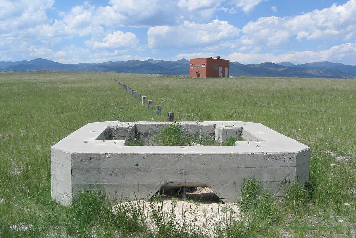
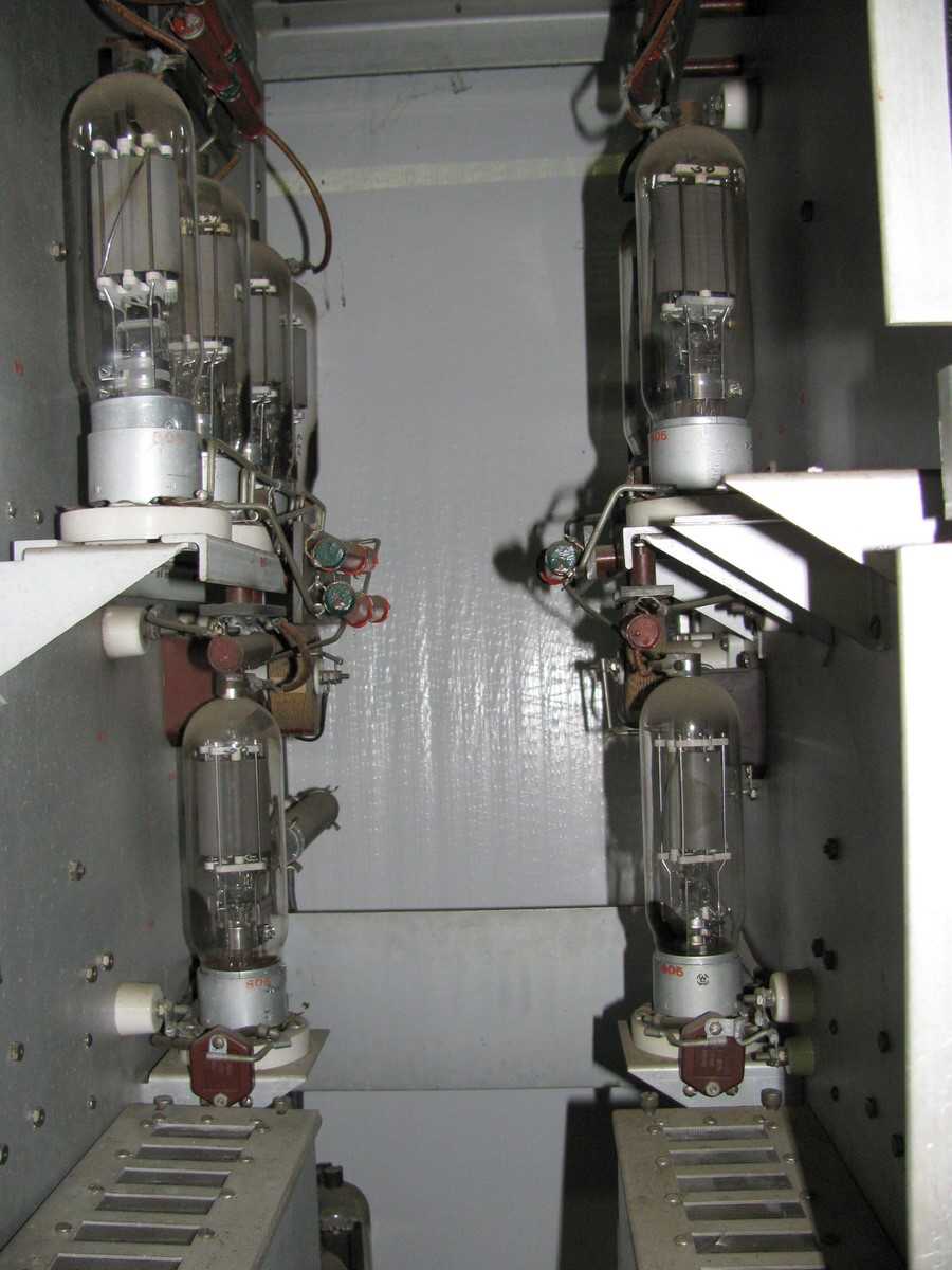
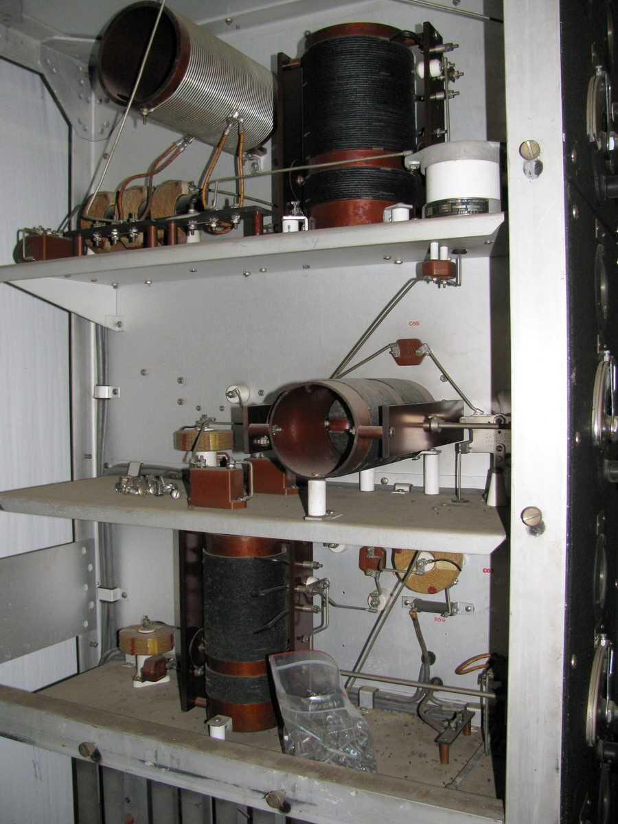
From the chart?s approximate positions it is often possible to determine an exact position using a National Geodetic Survey online search tool to find possible survey marks. This process found precise survey marks still on record for 10 of California?s 35 LFR sites. An online search of topographic maps located 8 additional LFR?s, six on the large-scale (1:24,000) maps. Searching the area on Google Earth and Bing Maps aerial photos has sometimes, when structures have be undisturbed, been the only means of exactly locating a LFR site. This is possible since, unlike the case with airway beacons, most LFR installations covered a 600 by 600 foot or 8+ acre site. On the site there were typically five approximately-120-foot antenna towers, mounted on concrete bases, plus a central building housing the transmitter and a standby engine/generator set. One tower was at the center of the site near the building with the other four towers at the edges of the square area.
The next, and potentially most-exciting, step has been to search the aerial photos to see if any features of the LFR still remain today. In the greater Bay Area, ranges were located at near the Hamilton, Moffett, Oakland, and San Francisco airfields. At Hamilton, the range was later converted to a non-directional radio beacon and the central building and center antenna tower are still standing. Aerial photos (search lat/lon: 38 05.50, -122 30.48) also clearly show the bases of the four outlying antenna towers. The Oakland site, west of Doolittle Drive and north of the north field or original airport, has not been reused and the concrete foundation slab of the central building can be seen in aerial photos. Exploration at the site, on the ground, revealed electrical junction boxes, partially-buried wiring extending to an outlying antenna tower site and broken red glass from obstruction light covers. It was impossible to determine exact locations of the San Francisco and Moffett sites and, in any event, the areas appear to have been reused or built over.
Features of seven other California LFR sites are still visible from the air! The most intact site, which is possibly the most-undisturbed in the nation (!), is near Fort Jones, about 31 miles WNW of Mount Shasta and 31 miles south of the Oregon state line. The aerial photo shows the central building and four of the five antenna towers still standing. After driving by on a trip to Seattle, I made contact with people in the local Scott Valley Pilot?s Association to arrange a visit to the LFR site. They were very hospitable and arranged with the property owners for a visit to the site in exchange for my speaking about airway beacons and low-frequency ranges at their monthly barbecue. The ranch owner related that when the CAA had leased the site in the 1930?s his father had signed an agreement that the government would remove all structures when they were no longer used. When the range was shut down in 1965, however, the FAA offered a new agreement that, in exchange a small payment, the government could simply walk away. Hence, we have a unique piece of aviation history in far Northern California!
Another case of "walking away" appears to be at the Whitmore LFR site, in a very rural area about 18 miles east of Redding, CA. This range was commissioned in 1944 and, apparently due to the efforts to conserve steel during WW2, used wood utility poles for antenna towers. A number of the pole-to-pole antenna wires were still in place when I visited the site 64 years later! Another northern-California LFR commissioned during 1944 served the Alturas Army Airfield. The Google Earth/Maps view (search lat/lon: 41 34.688, -120 42.922) clearly shows the Alturas central-building (or its slab), the five antenna-tower bases and even the supports for the cables from the central building to the towers! At Red Bluff, as at other locations, the central antenna tower is currently used by a non-directional radio beacon with the concrete bases of the four outlying antenna towers still in place in an open field. At some similar installations, such as Miles City, Montana, today?s radio beacon still operates on the same frequency as the 1940?s range station!
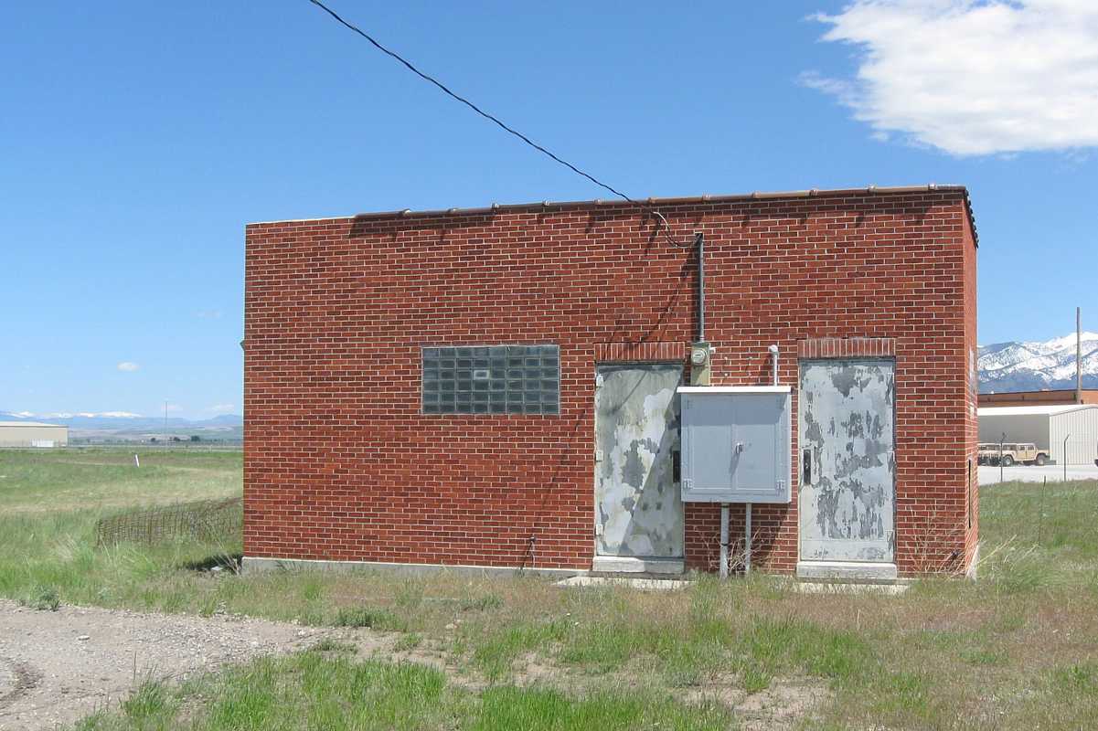
Driving to Montana in 2008 to explore airway beacons and discuss their current use in the state with Montana Aeronautics Division people in Helena, I was able to explore seven LFR sites in Montana, Idaho and Nevada. Five sites had red brick central buildings with glass-block windows, a 1930?s architectural fad. The site at Whitehall, Montana had interesting wood-post cable supports between the central building and each of the five antenna-tower bases. At Bozeman, the red-brick central building is easily accessible on the property of today?s airport.
On a 2009 trip to Utah, I explored the LFR sites at Fairfield, Plymouth, Salt Lake City and Wendover. At Wendover, I thought I would be able to walk about 100 feet across the salt flats to the base of an antenna tower but, on the first step, I sank ankle-deep into the "slush" beneath the surface! In the summer of 2010 I hope to visit seven sites in California, Oregon, Washington and Wyoming.
Notes:
1
Komons, Nick A. Bonfires to Beacons: Federal Civil Aviation Policy under the Air Commerce Act, 1926-1938. Washington, D.C.: Smithsonian Institution Press, 1989 (page 155)
2
Pilots? Radio Handbook, C.A.A. Technical Manual No. 102. Washington, D.C. U.S. Government Printing Office, March, 1954 (page 44)
