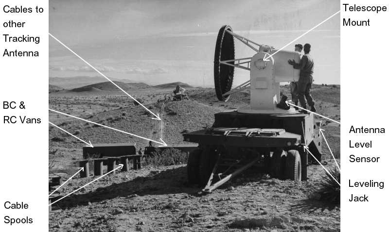
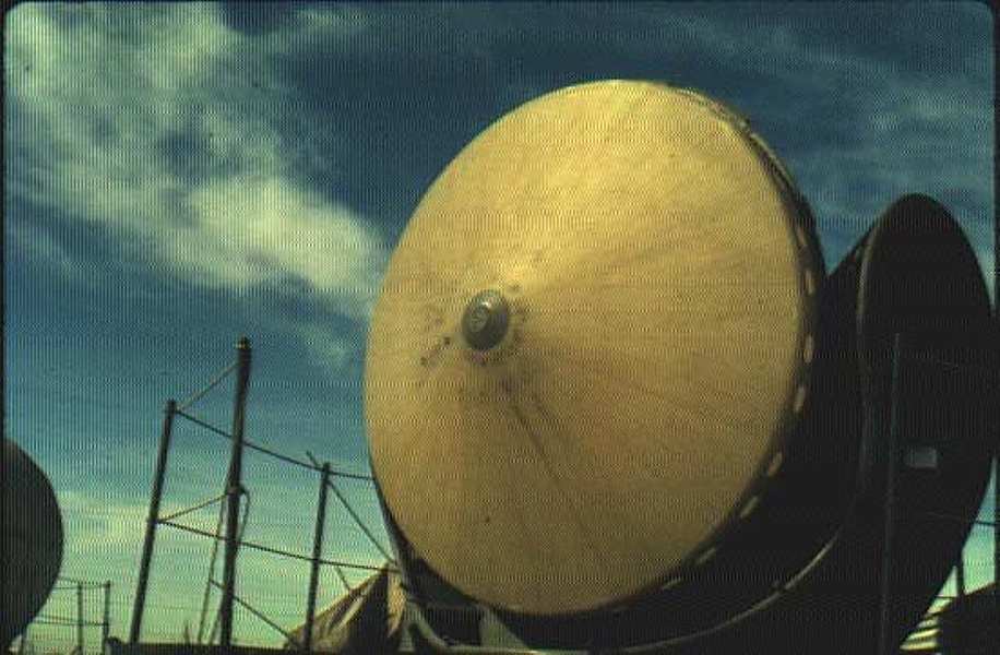
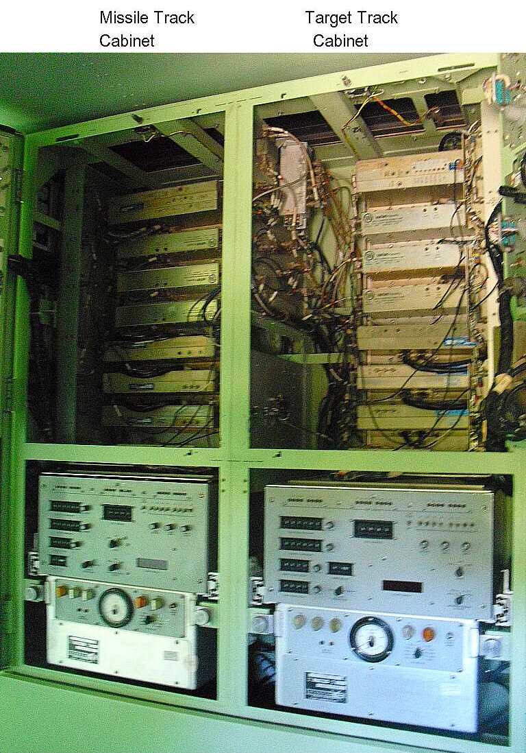
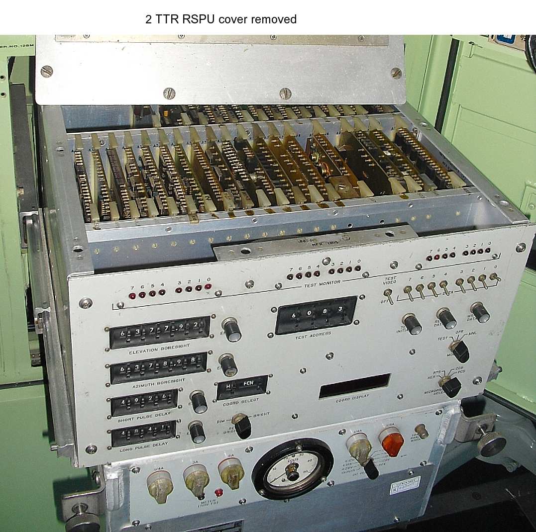
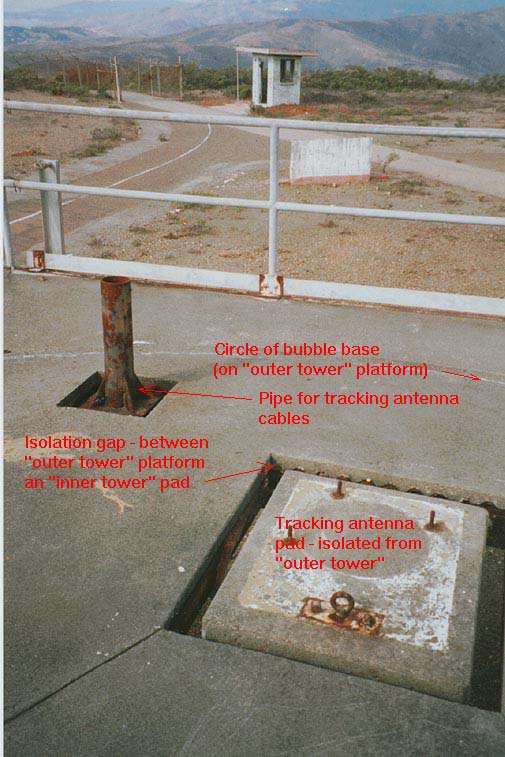
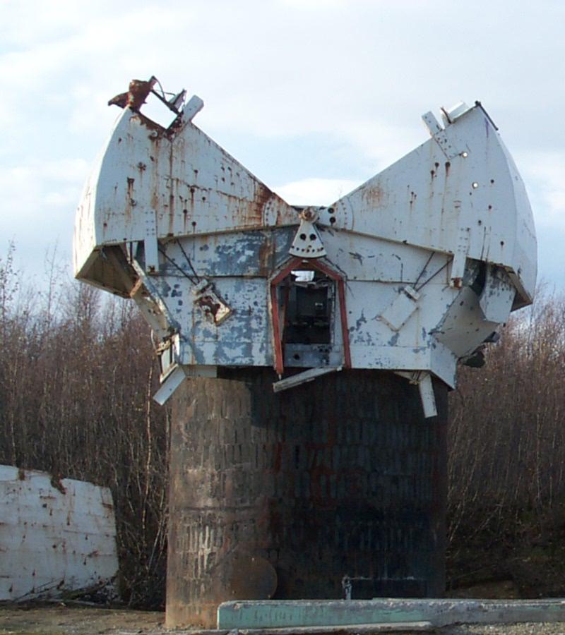
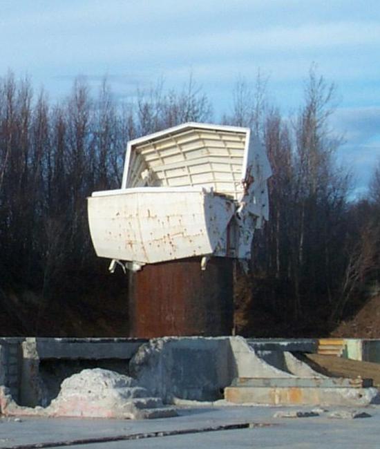
As mentioned above, the external appearance of the Missile Tracking Radar (MTR)
was identical with the TTR above.
|
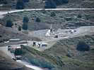
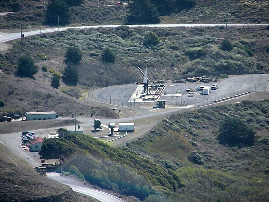
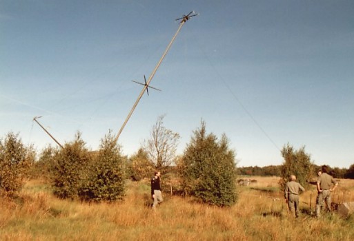
In addition to needing a view of the target volume, into which it guides the missile,
the MTR also need a direct view of the missiles on the launchers.
photo courtesy of Greg Brown, of SF-88 launcher from the IFC area.
|
From Rolf Goerigk,
Specification for the Missile Tracking Radar (MTR) include:
| Antenna Gain | 44 dB
| RF Peak Power | 158.9 kW
| Average RF Power | (PRF 520 pps) = 79.4 Watt
| | |
|
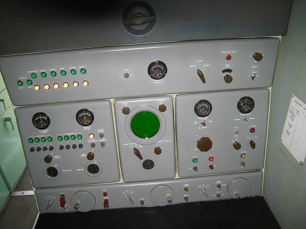
There is one missile tracking operator with one a-scope. The missile tracking signal
is a radar pulse generated by the missile in response to a pair of radar pulses
transmitted by the missile tracking radar.
The missile "echo" is quite strong and gives a high "signal to noise ratio" and
looks like the
strong target tracking signal above. The missile is always tracked in
"automatic" mode. When every thing is working correctly, the missile
operator observes the equipment for proper operation,
but does not have to touch the equipment during missile firing operations.
|
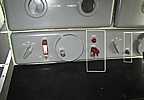
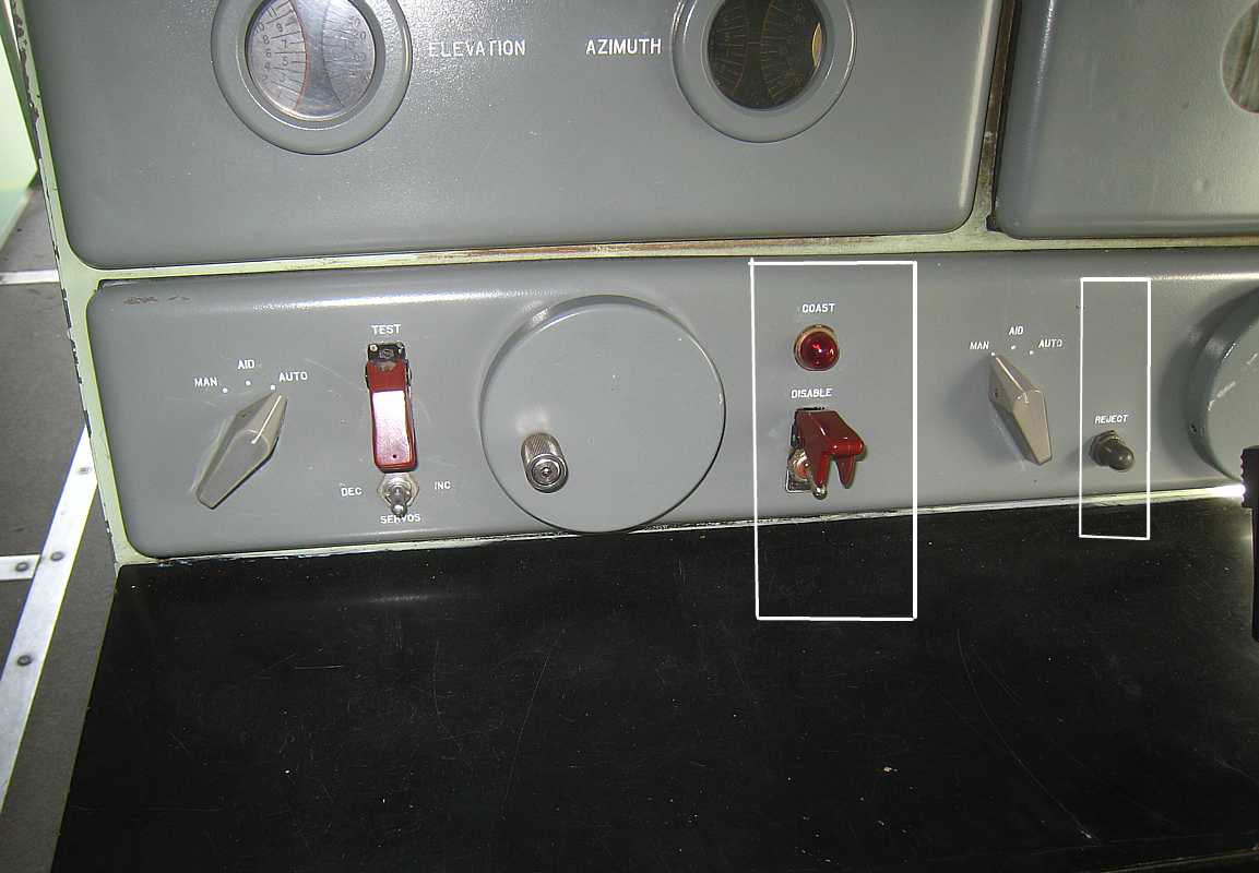
Missile Tracking is a little different from Target Tracking
- Automatic Frequency Control tracks missile magnetron not track radar magnetron
- An automatic range coast function, three seconds (large white box)
- Missile reject button and signal, request a different missile (small white box)
| |
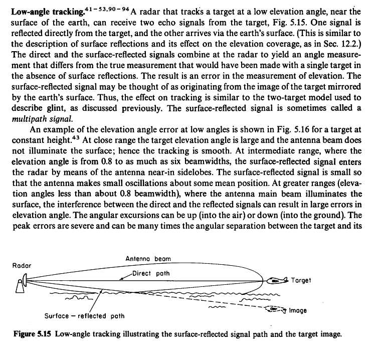
There is one interesting "got cha" - the MTR can lock on to the *ground reflection* of the
missile's transponder. (Radar waves bounce off the ground as well as metal and water.)
The missile tracking operator must observe that the elevation angle of the MTR is correct
when locking on the missile. This can be called "multi-path, a pest even for FM and TV reception.
If locked on the ground reflection, the MTR will slew *down*
when the missile is launched - causing loss of tracking of the missile during launch -
and things happen so fast that there is no recovery from this error. The missile will
go straight up, detect that it is not being tracked, and explode in about 4 seconds. :-((
The only practical thing is to slew to and lock onto the next ready round and fire that.
The loss of time should be less than 10 seconds :-((
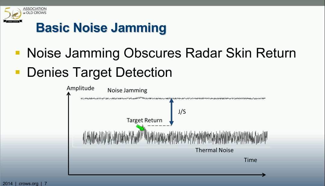
Since the missile tracking radar is not pointing at the target until the last few
seconds, the airborne enemy jammers only "see" the MTR for the last few seconds and
have much more trouble jamming it, especially with the high signal strength
of the transponder on the missile. The possibility of an enemy plane tracking
a Nike missile in order to jam it (cause it to fail to see the MTR
or to act on false steering and burst commands) would seem to be slight.
The time delay between the missile receiving the missile tracking radar pulse pair
and the generation of the response is fixed, and allowed for in the MTR range system.
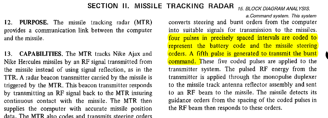
Missile Commands - Communication systems to command the missile
The Ajax and Hercules missile systems use different communication systems
(using the Missile Tracking Radar) to command the missile.
- Ajax Command System
- Hercules Command System
- Hercules Command System - Battery Code
Ajax Command System
|
In the Ajax system, missile steering commands are sent to the missile by the
missile tracking radar
by changing missile tracking radar pulse rate. You can think of the commands as
"tones", one tone range for up/down, another tone range for left/right, another
tone for burst. The tone signals are combined and control the generation
of radar pulse pairs.
|
Hercules Command System
In the Hercules system, missile steering commands are sent to the missile as follows:
Pitch, yaw and burst commands are not mixed as in the Ajax but are sent out
individually. One command is send out each 2,000 microseconds (500 commands per second).
Pitch and yaw commands are sent as two pulse pairs. Lets call the first pulse pair
the "start" pulse pair, and the second pulse pair the "command" pulse pair.
The "start" pulse pair are separated in time by the site specific
delay (called "missile code").
The command is a pitch command if the "command"
pulse pair is separated by one missile code plus one microsecond.
The command is
a yaw command if the pulse pair is separated by one missile code plus two microseconds.
The delay time between the last pulse of the first pulse pair and the last pulse pair
is the value of the command. The delay time for -7 g is 52.5 microseconds.
The delay time for 0 g is 87.5 microseconds.
The delay time for +7 g is 122.5 microseconds.
The Pitch and Yaw commands are sent alternately during normal tracking until 0.5
seconds before intercept. First the pitch, then the yaw, then the pitch, ... .
Due to the coding, the missile knows which command is which type.
During the boost phase (4 seconds) and the roll phase (1 second), zero g yaw and
pitch commands are sent to the missile. Then normal steering commands are
sent to the missile, which is normally starts as a dive (from vertical)
to the predicted intercept point.
The burst command is a special series of pulses starting 0.5 seconds before predicted
intercept. No steering is performed during this final 0.5 second interval.
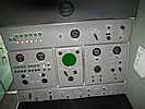
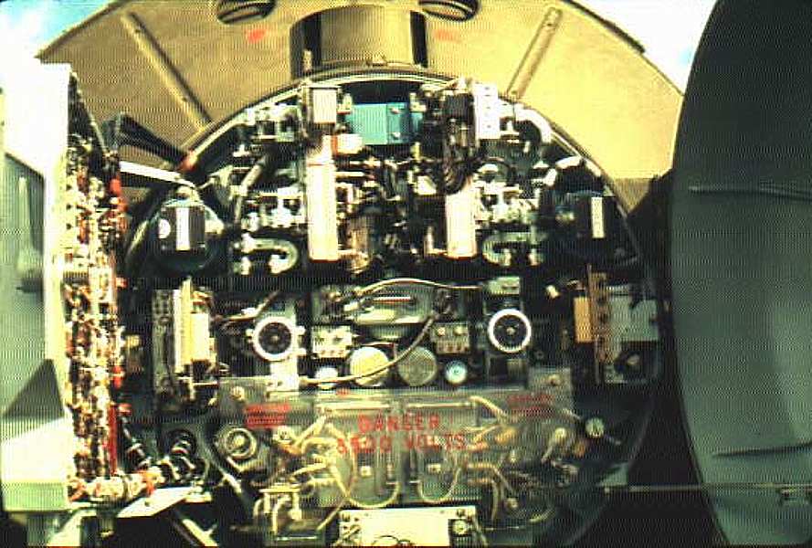
The following images are all from the the RC van, by Greg Brown.
Battery Code Panels
|
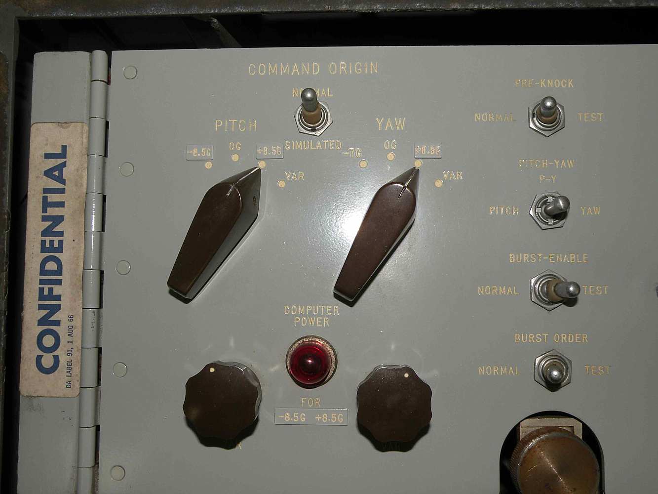
Command Origin Chassis
|
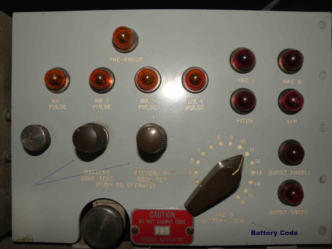
Battery Code Panel
|
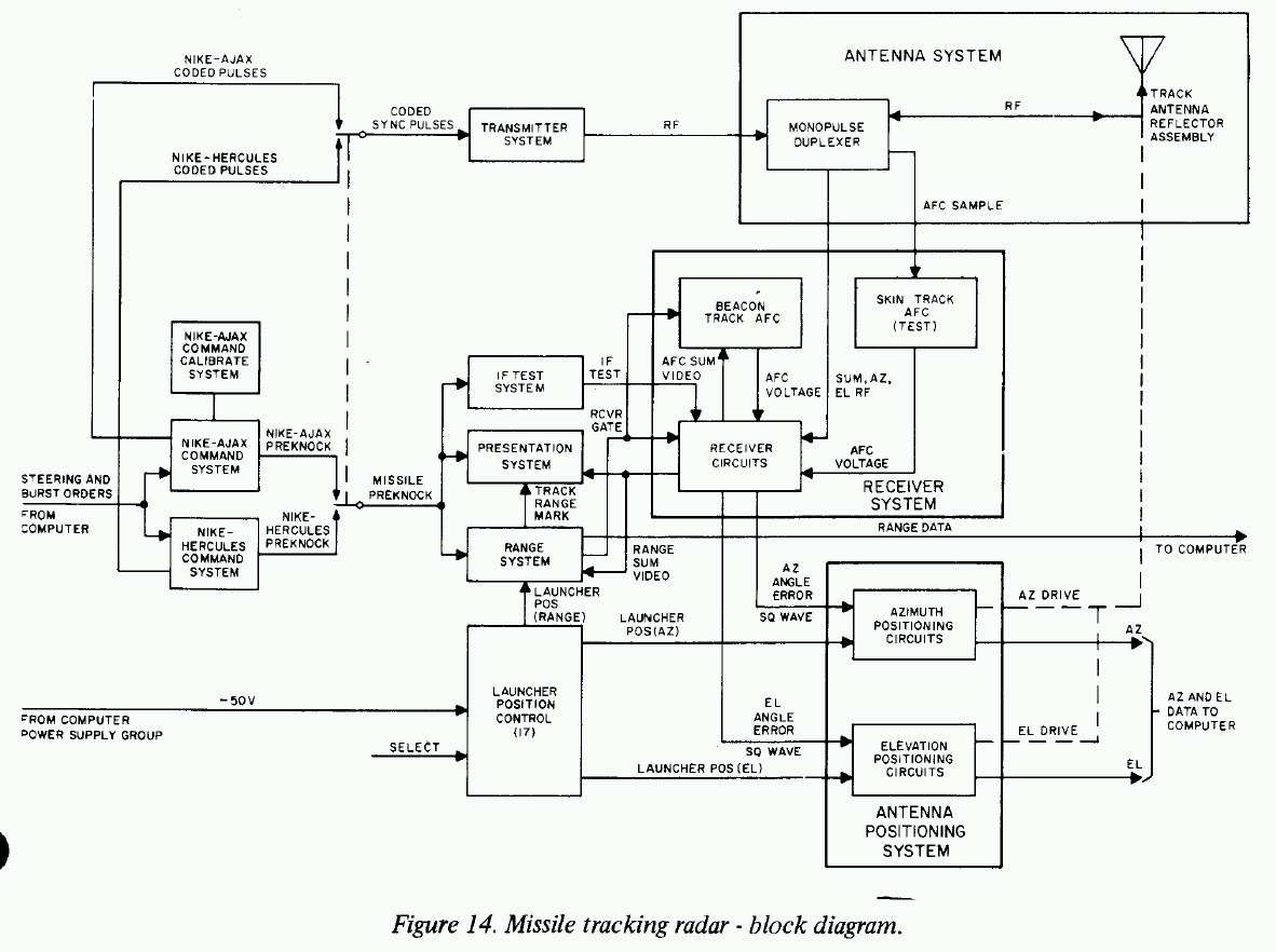
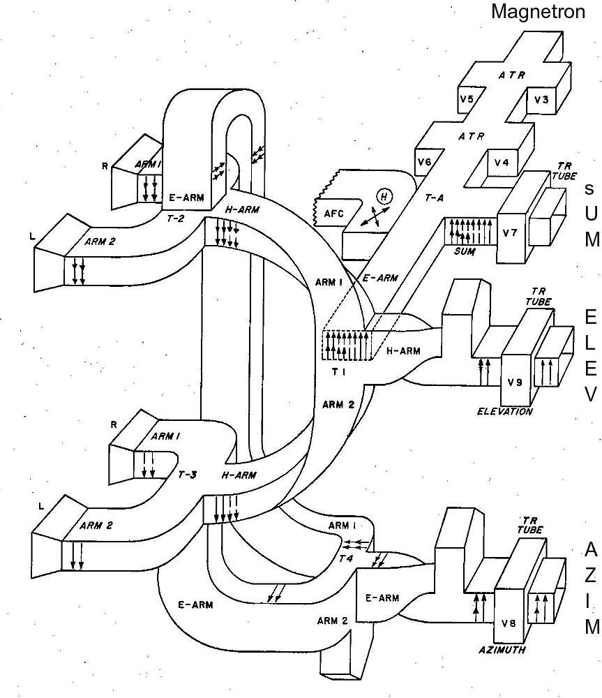
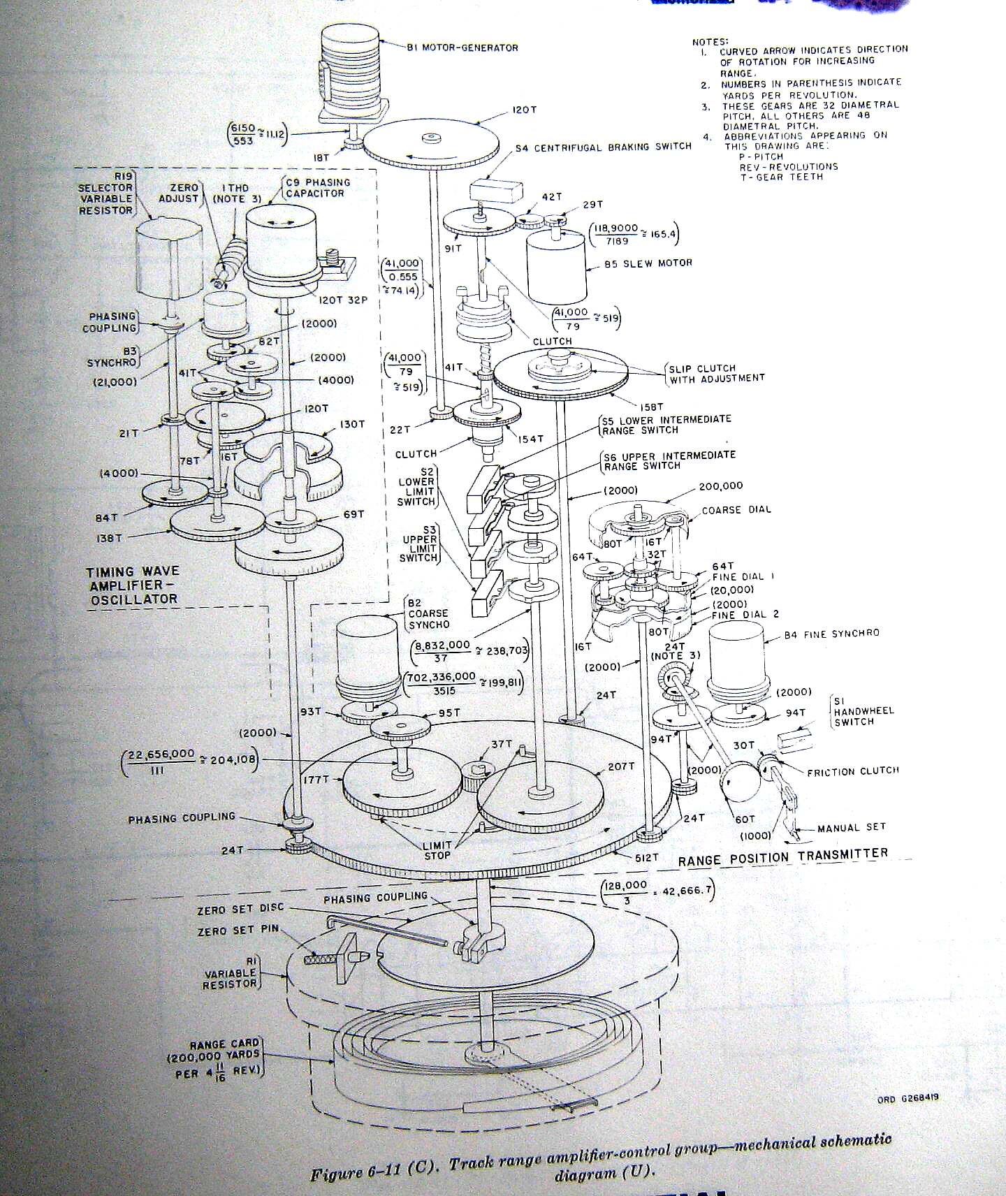
Figure 14. Missile Tracking Radar, Block Diagram
|
Hercules Command System - Battery Code
|
Greg Brown found the following chassis and document dealing with "Battery Code". Since it wasn't mentioned in
the document above, and doesn't specify down to
the microsecond, I'm confused. Or maybe too old a puppy :-((
Page 18, section 15A of Lesson 4 of MMS SUBCOURSE NUMBER 150
|
The Missile Tracking Radar (MTR) pointing system had an added circuit to automatically
point the the MTR at the designated missile. If the MTR was not tracking a launched
missile, and this circuit was engaged, the MTR would slew (in azimuth, elevation,
and range) to the position of the designated missile. The Launch Control Officer
would select the next missile to be fired based on:
- warhead selection instructions from the battery commander (and area control)
- local knowledge of the best, most ready missile available for launch.
The position (range, azimuth, elevation) of each launcher was dialed into the
MTR system.
Return to beginning of Nike Radars
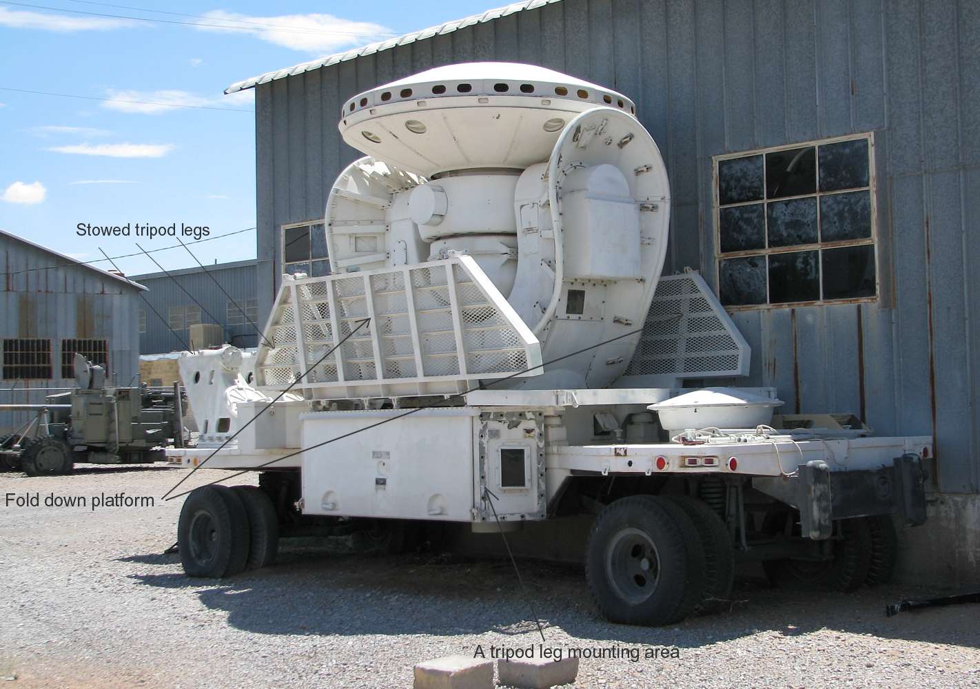
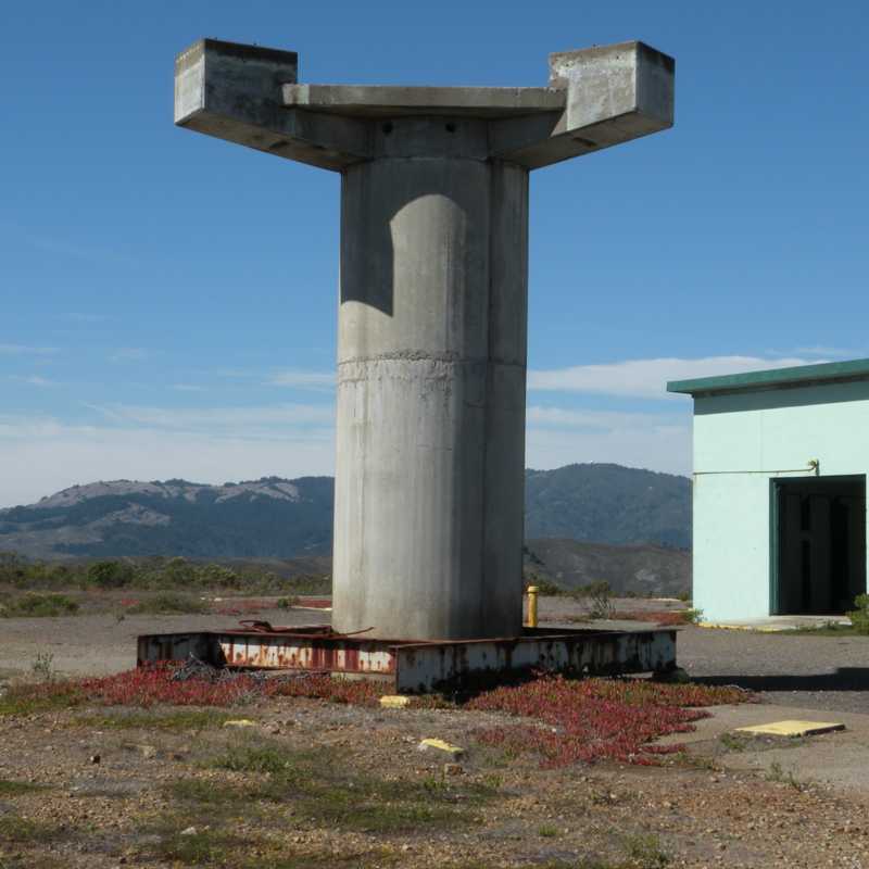
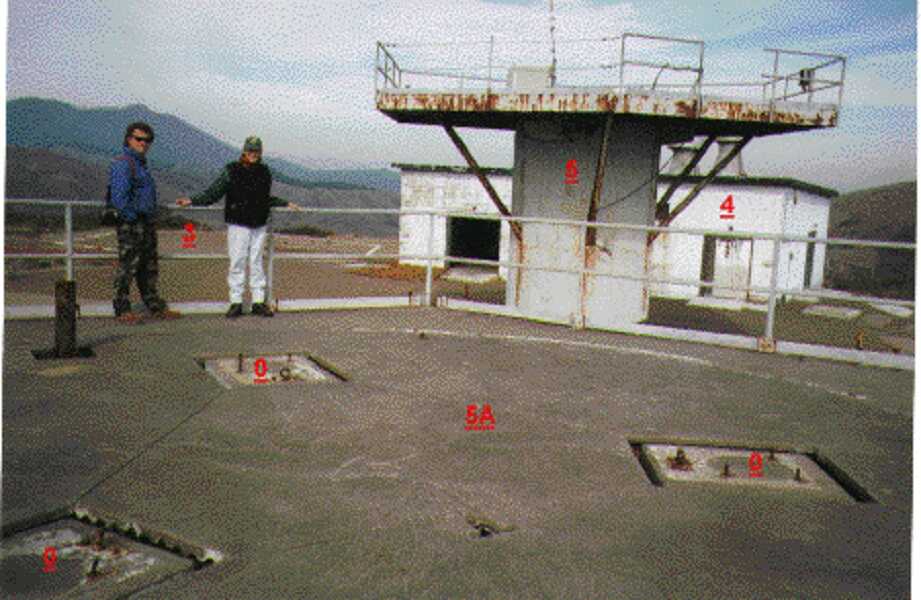
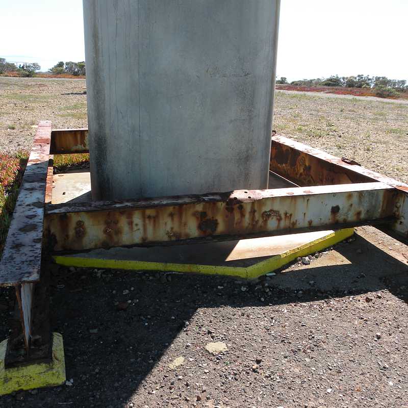

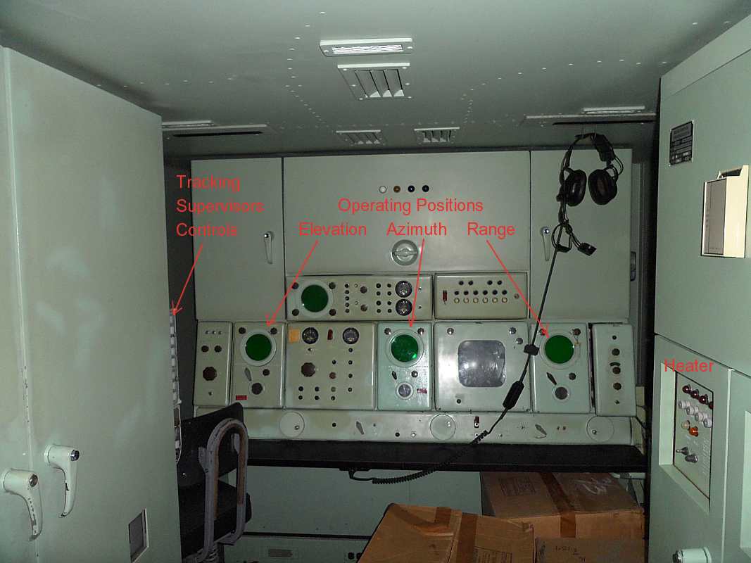
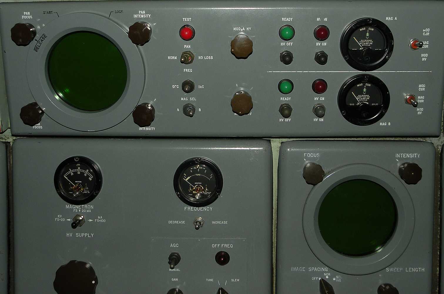
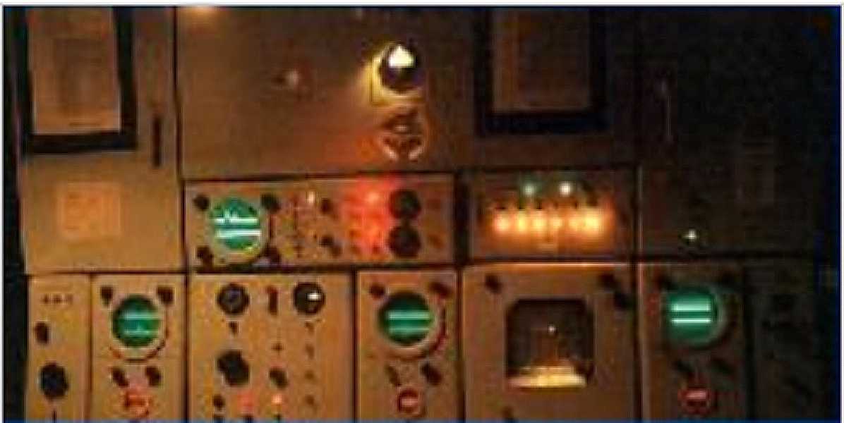
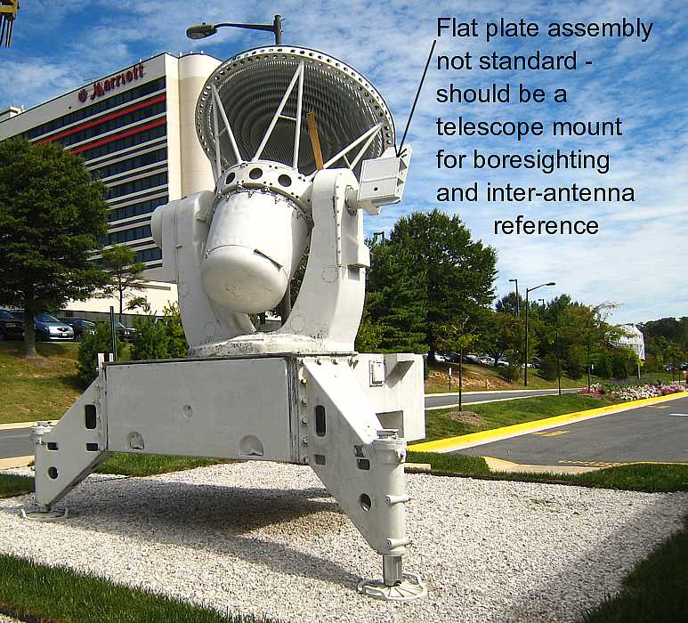
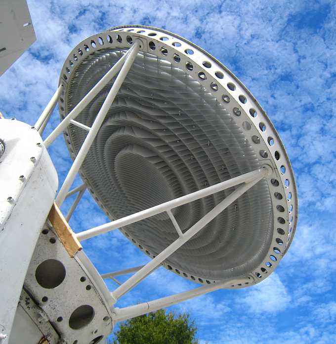
 Fig. 3-1&2
 Fig. 3-1&2
 Fig. 3-4&5
 Fig. 3-6&7
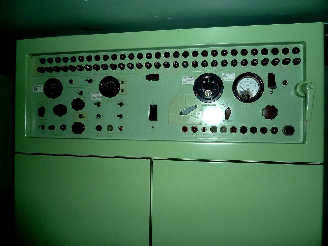
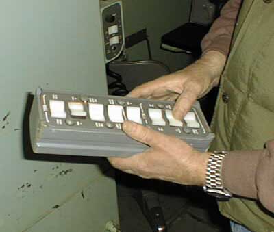 Anti-jamming control box used by tracking supervisor
